ext1
·Hello OF,
I just finished restoring a sorry looking JB Champion that had its horn chopped off and twisted to its rightful glory. I don't know if this information will be of any use to anyone, but I thought I'd share in case someone had the same issue as me.
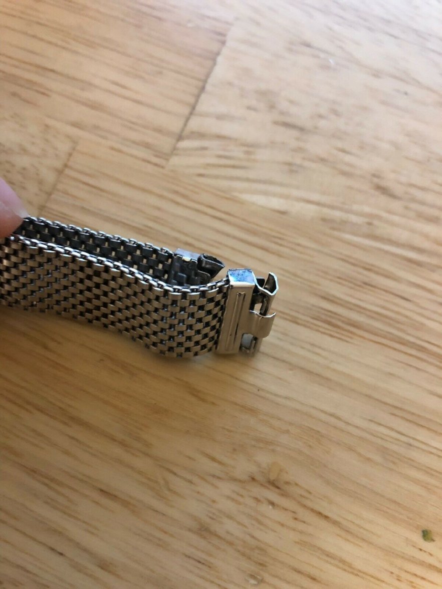
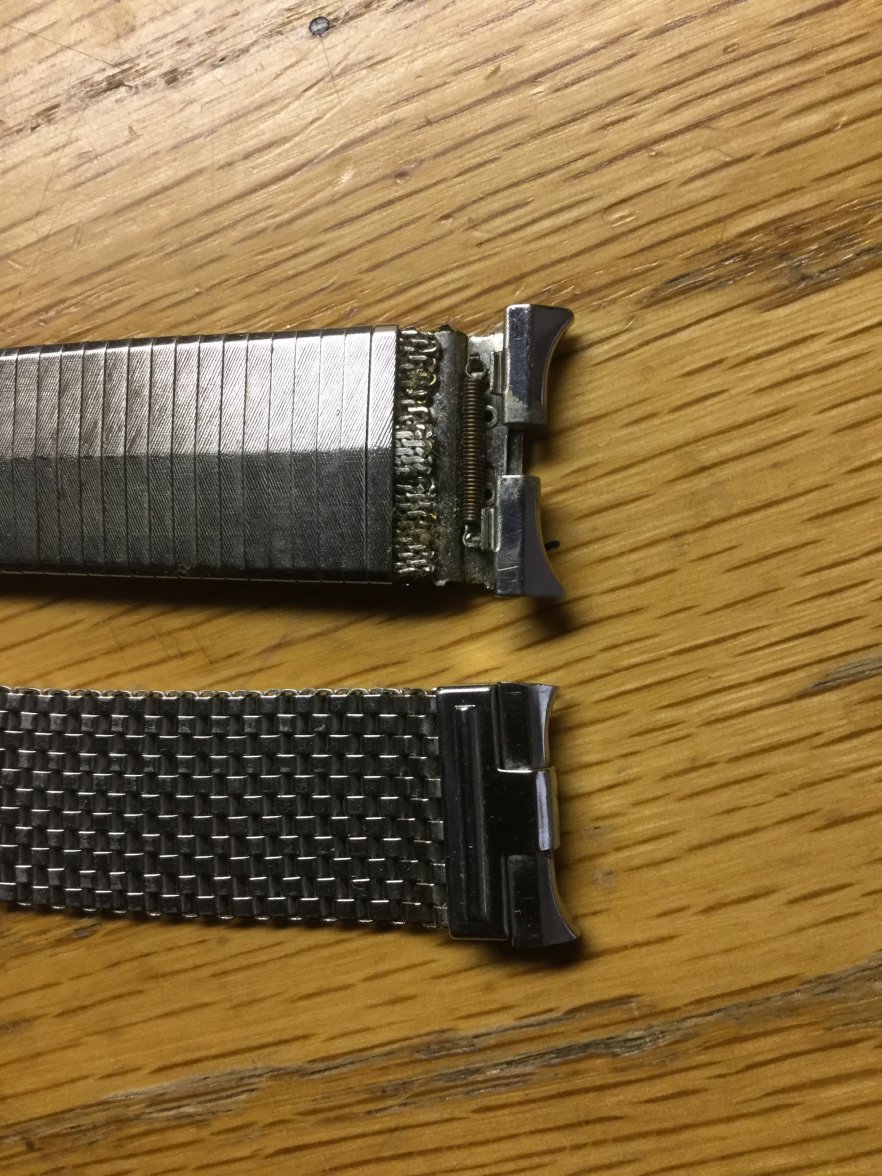
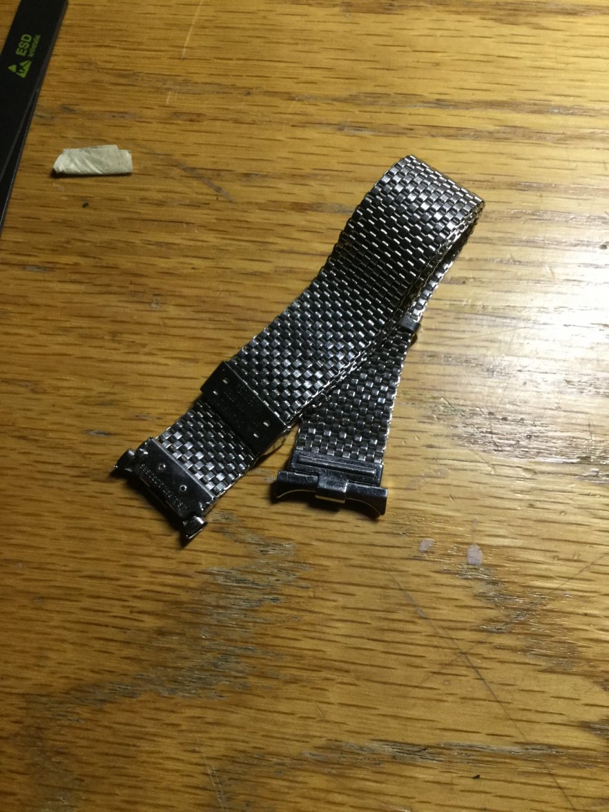
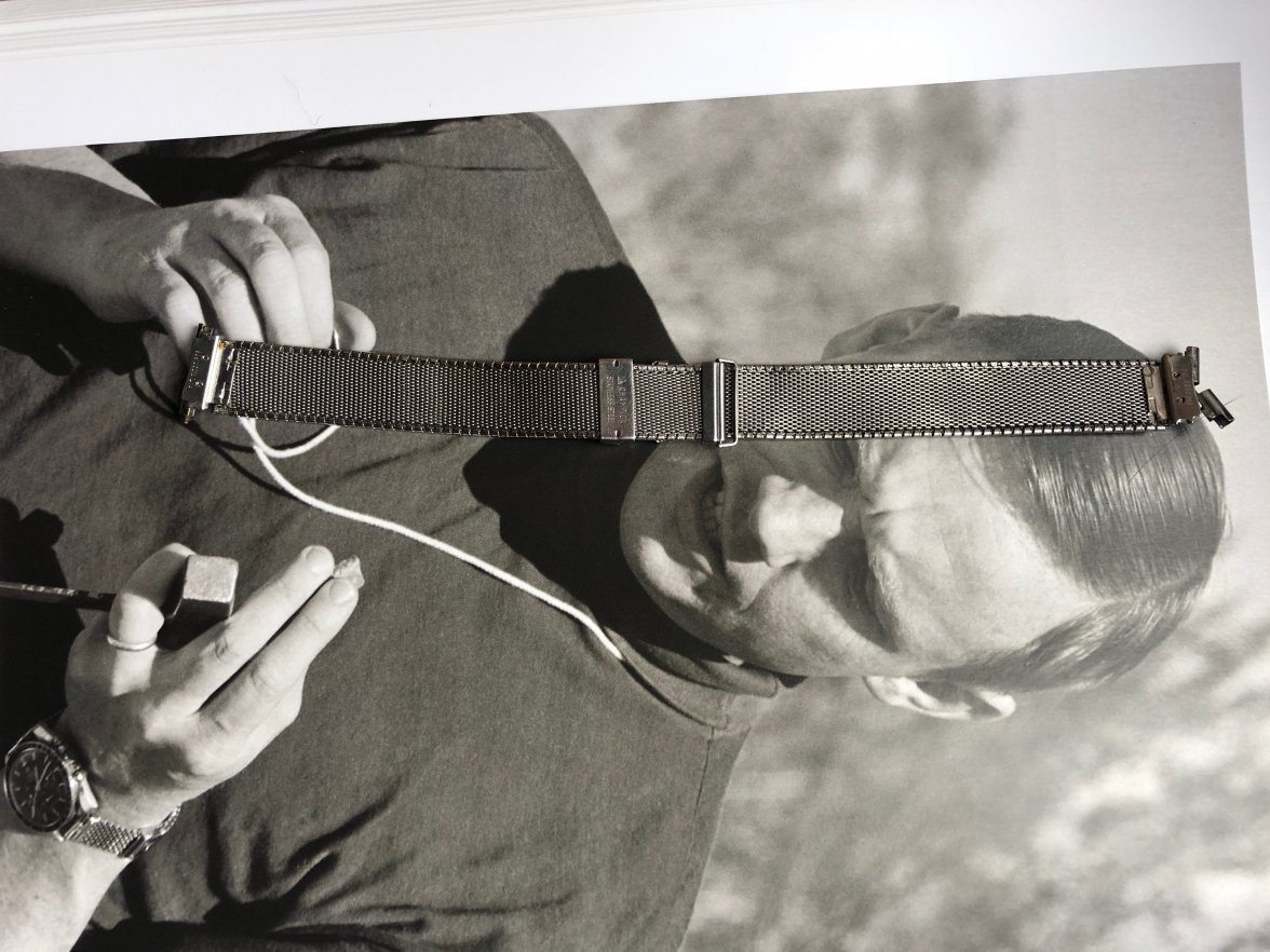
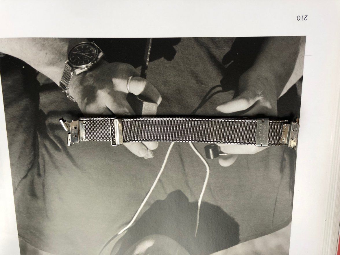
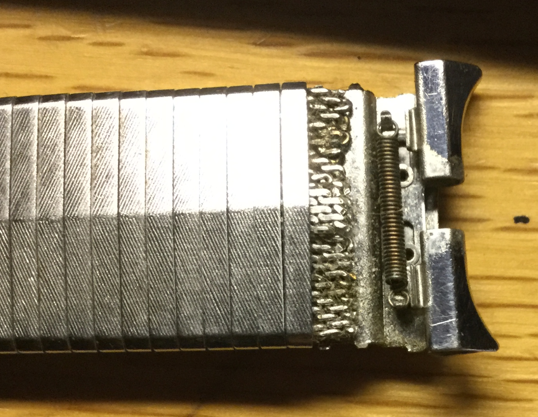
The bracelet in question, looked like this. Oww.....
Honestly this would have been a really easy fix only if that horn piece wasn't trimmed. Because the piece is trimmed, we have to replace the entire thing.
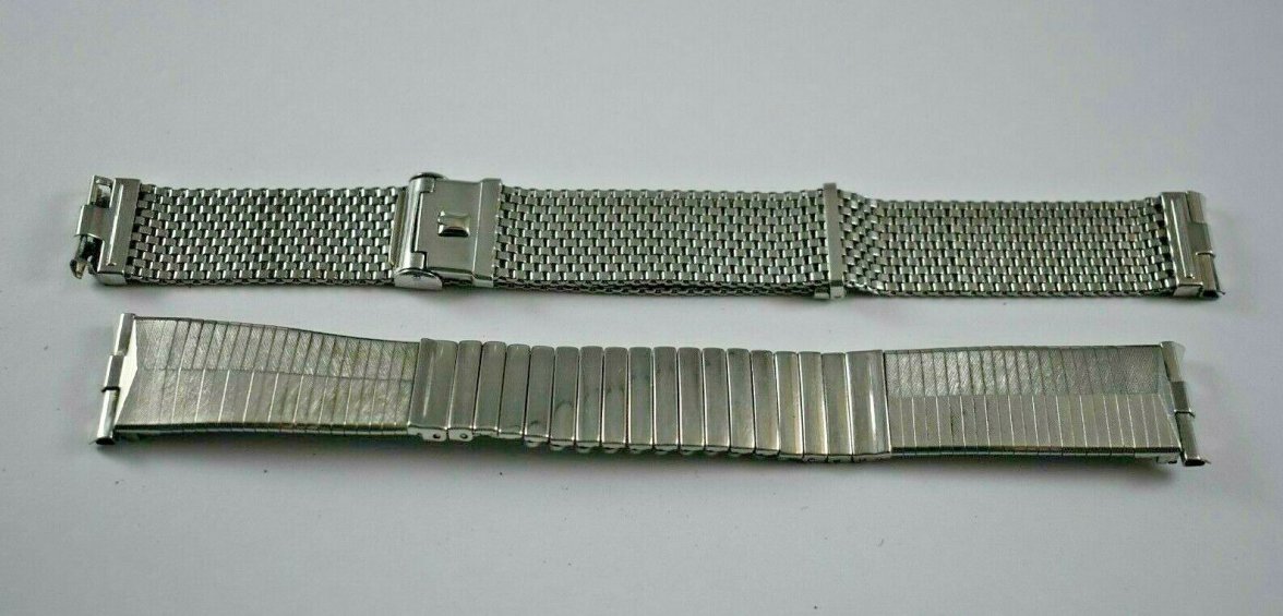
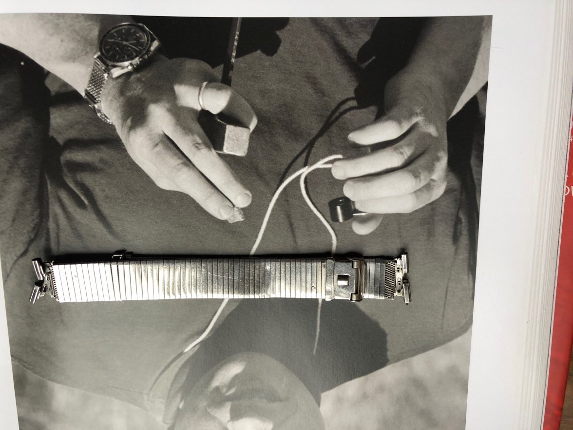
The bracelet on the bottom is the donor bracelet. It valiantly gave its life to save its more expensive brother.
I sat down at 10pm, and I remember lifting my butt off the chair at 4am. So after 6 hours here's what happened...
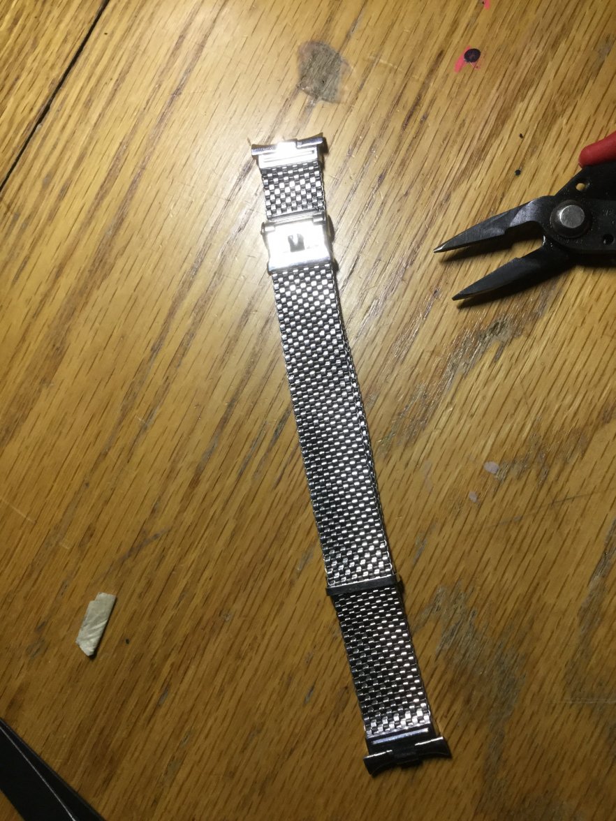
Perfect! Very happy with the result.
So here's the process. To successfully dismantle this thing, we have to understand the anatomy of the bracelet. I have been reading @TLIGuy 's excellent posts about the bracelets and that's where I got most of my structural background knowledge before actually handling one in person.
Here is the patent for the bracelet that @TLIGuy also posted before here.


This is quite confusing, but as we go through the guide you will see how the parts work and correspond to this diagram. This diagram will also be helpful for me to refer to the things you will see in the picture. You will notice that the bracelet at hand does not fully match the diagram as well - so keep that in mind.
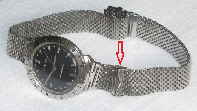
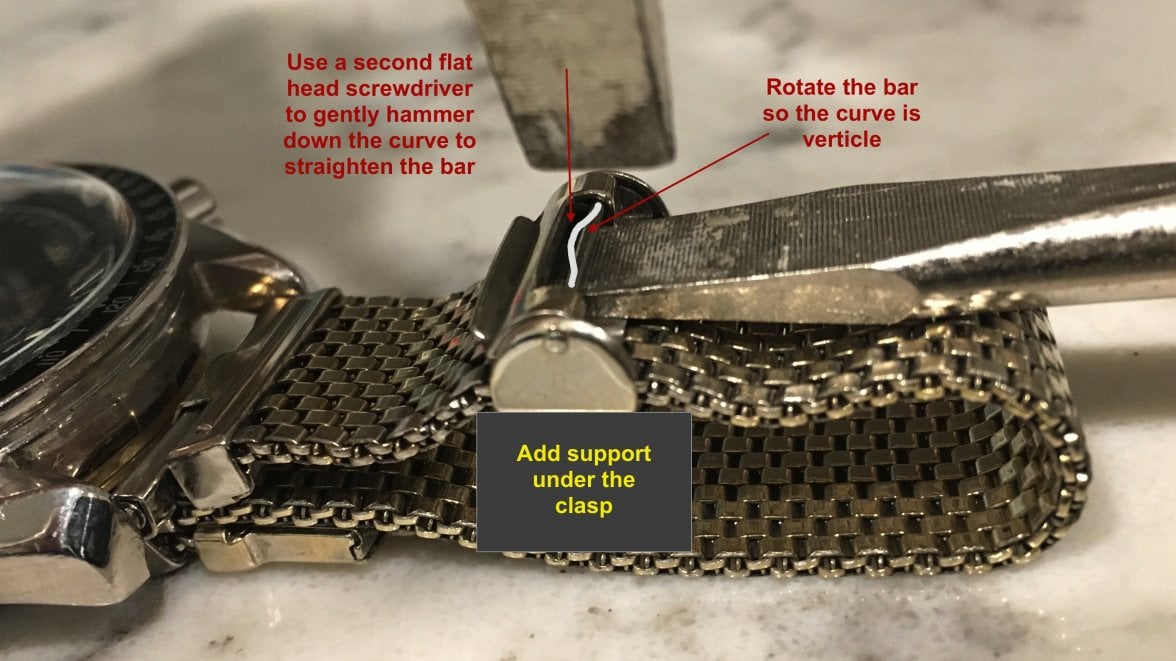
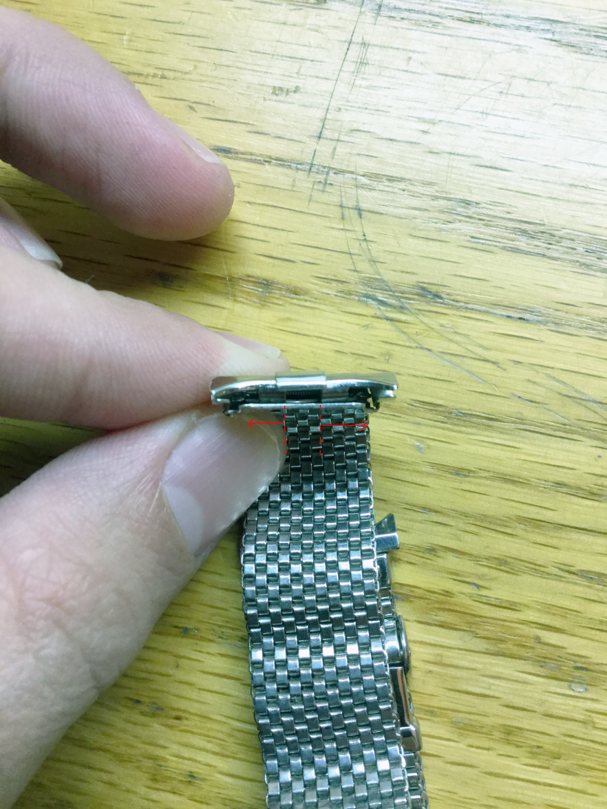
Anyway the first step is to pry off what looks like to be piece 96, or what I will call the top cover piece. I followed the steps outlined here by @Stuie. (Great guide by the way if you want to shorten your JB)


(Pic reproduced here for convenience. Original pic of @Stuie. Forgot to take pics of disassembly)
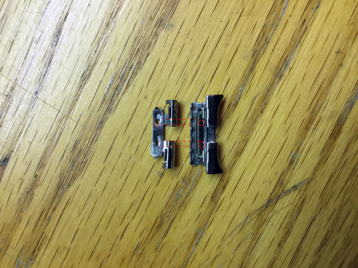
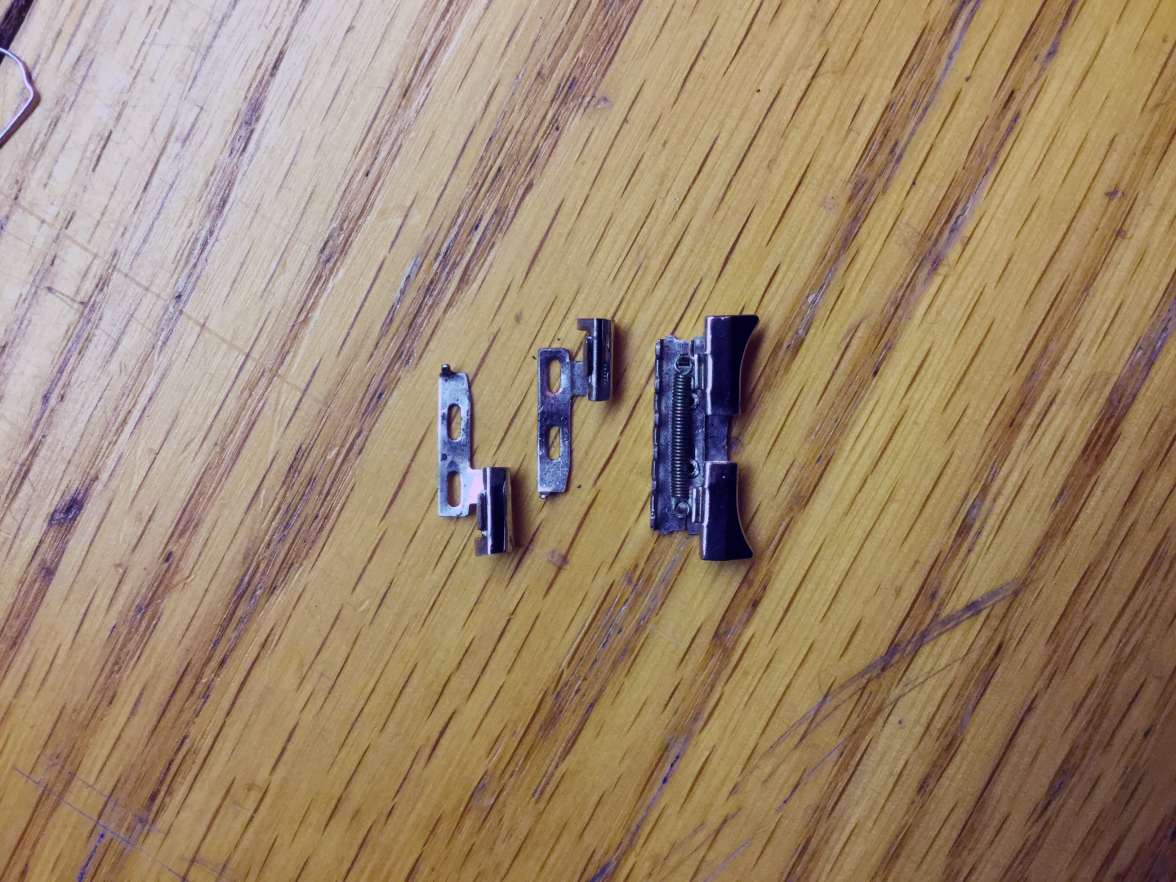
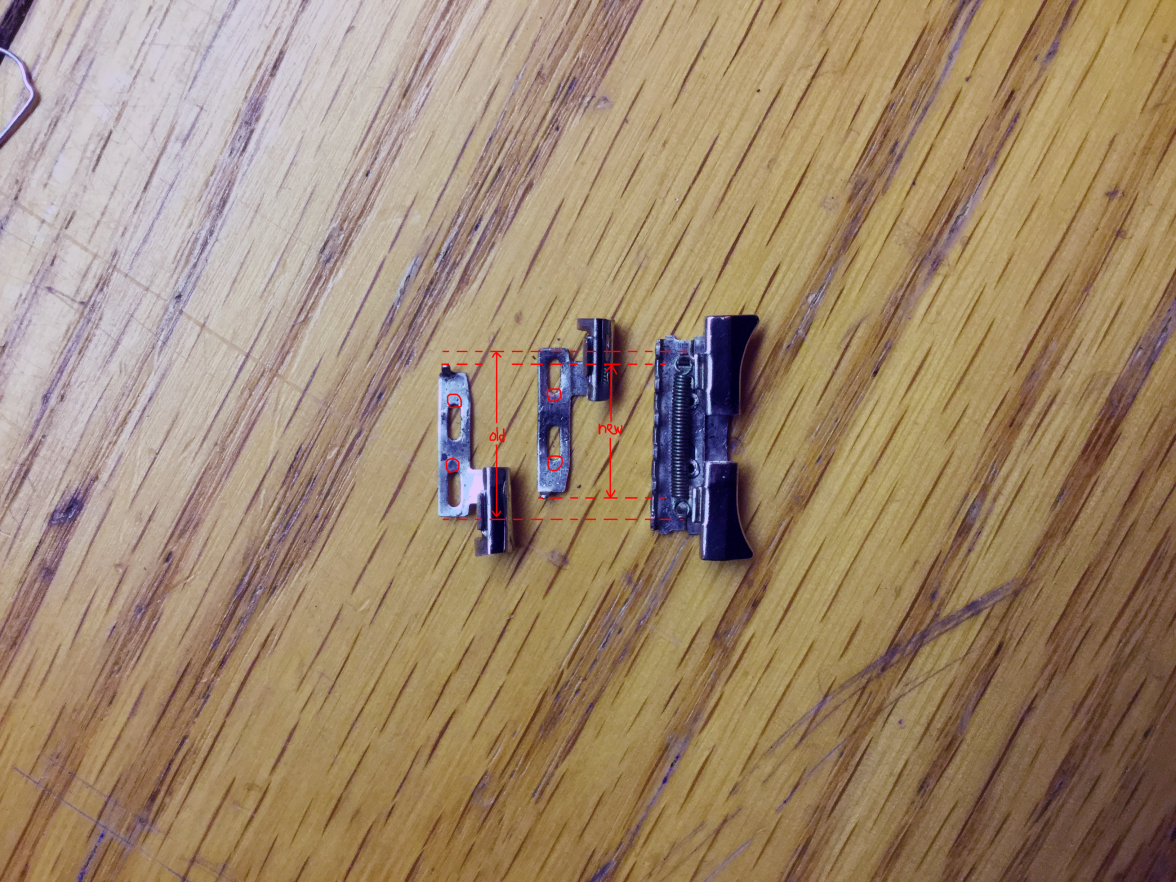
So the first part to the left is piece 96, aka top cover piece. The piece to the middle is the spring/lug assembly, what looks like to be consisted of piece 50, 66, 64, 80, and 74. Here is what that middle piece looks like in detail.
I removed the donor's top cover piece first to check out the mechanism. Behold it in action!
(Pardon my nails...but they were a very useful tool during this operation. I swear!)
You can see that there are two pieces of horn (part 64 and.. 66?) that move side to side and expand using the spring (part 80) inbetween. You can also tell that something was wrong with the way the unfixed JB on the bottom was. Probably technically the mechanism isn't broke but it's hard to show it expanding and contracting since the horns were cut.
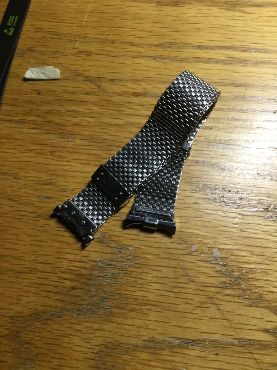
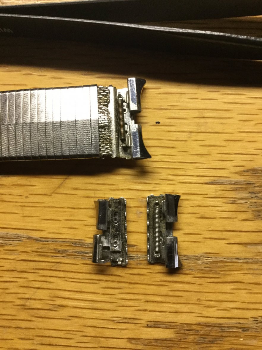
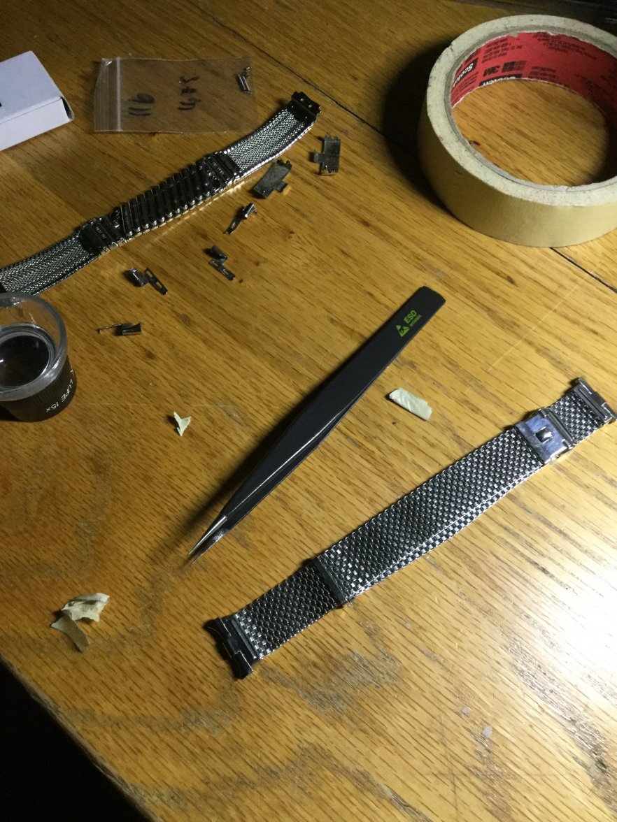
So here is the problem statement.
The one on the bottom left is the twisted part of the unfixed JB. The one on the bottom right, is the better of the two ends of the unfixed JB. However both are trimmed, so the horns need to be transplanted from the one on the top.
First we take out the spring. You can slide it out with whatever tool you wish. But make sure it doesn't go PING! and fly across the room!
If you zoom in you can see how the connector bit of the spring is latching onto the two horn pieces.
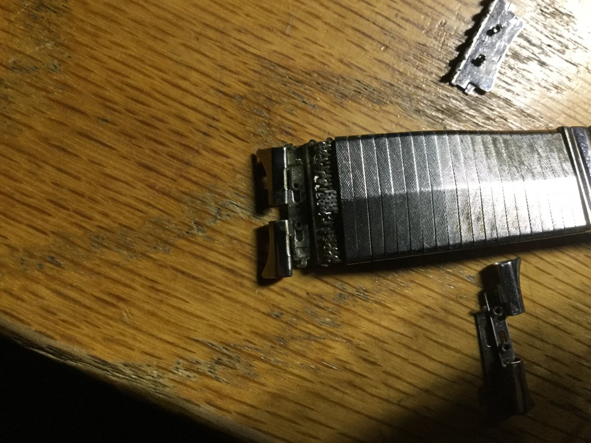
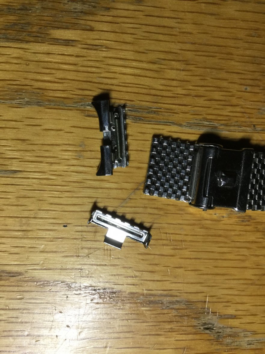
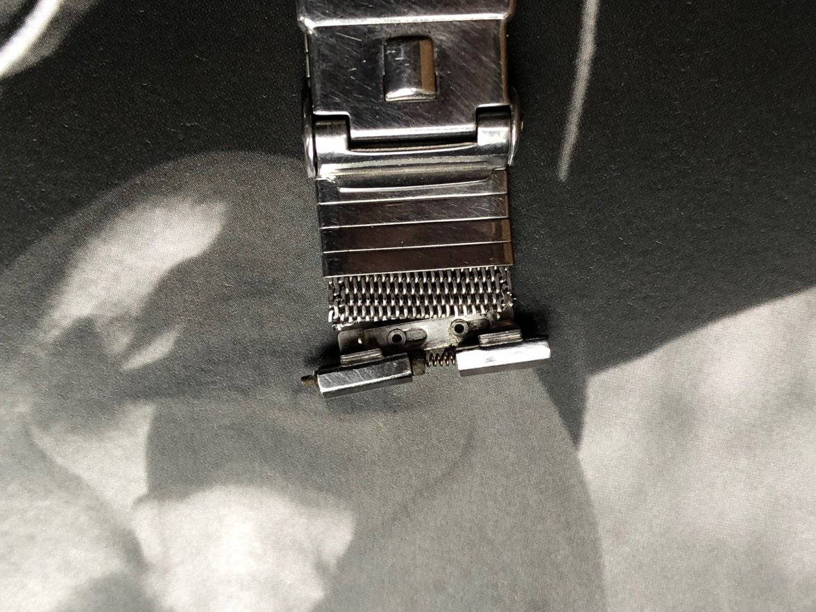
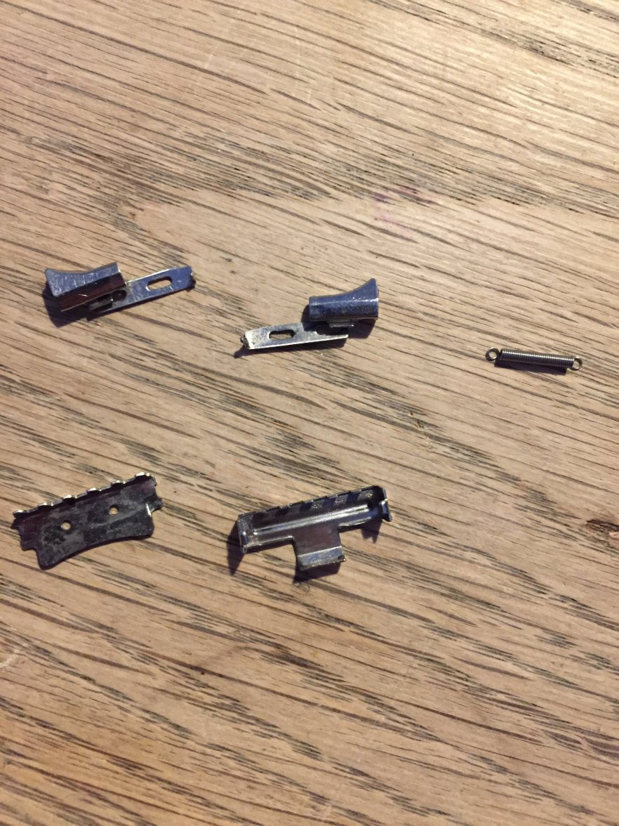
So with the spring out how does the module look?
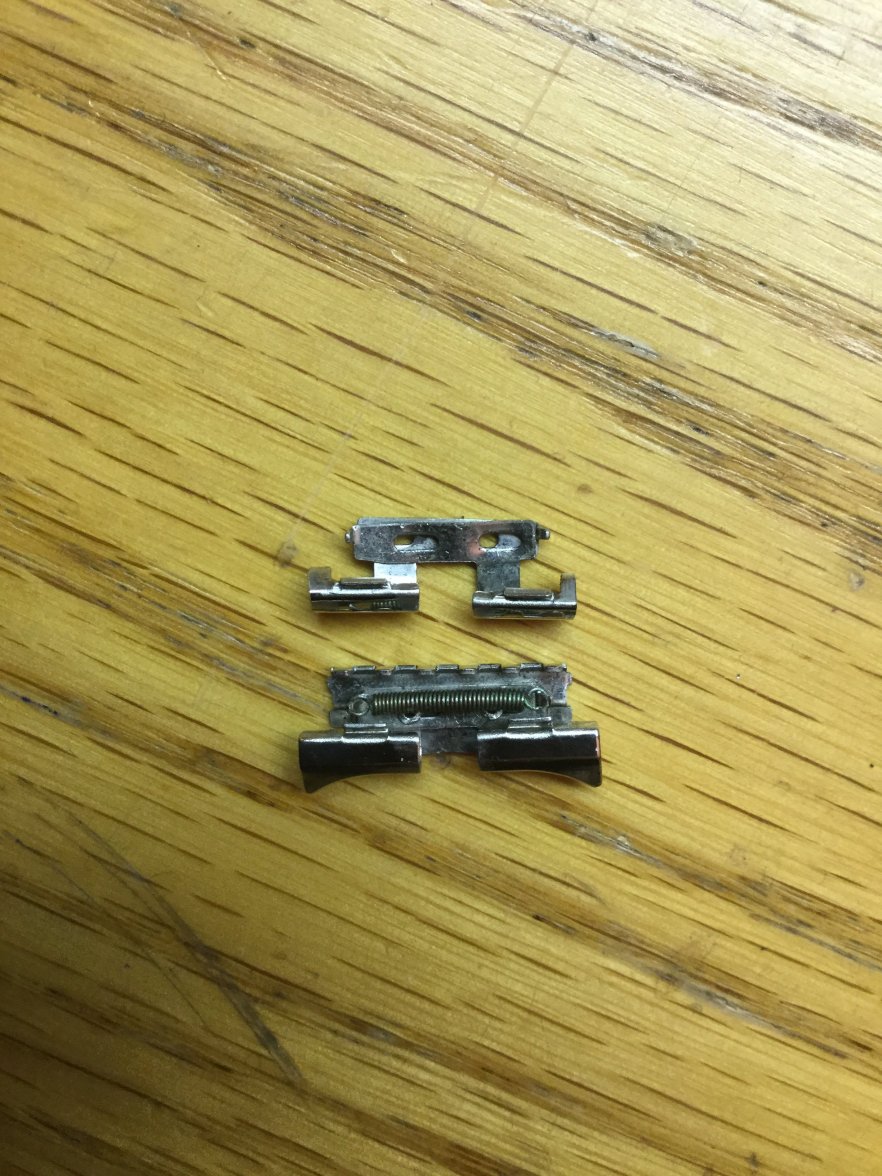
It looks like that, on the donor band. But here's the tricky part. The I-shaped connector (infamous part 74) connects the base (part 50) shown at the top, and the two horn pieces together. You can see the base still has the connectors. Normally only two connectors are used for the whole piece. (So that means I have two other horn pieces with no I-connector inserted between them elsewhere.)
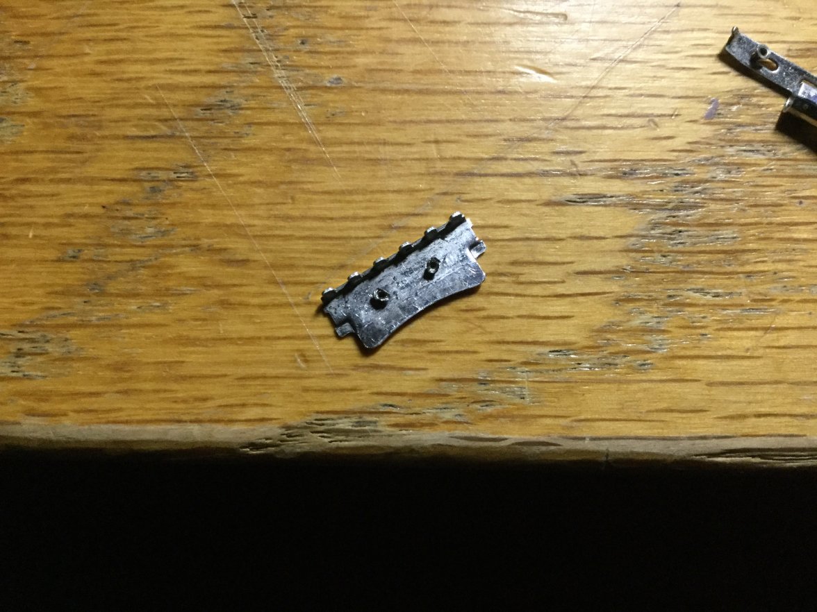
The part removed from the band looks like this.
So now the problem is to find a way to remove the two horn pieces from the base. You need to keep the original base, because the donor base doesn't fit the mesh.
First I tried to bend the horn pieces to find an angle to wiggle the pieces out.
It turned out to be very ugly. I went with the first attempt because the trimmed horn pieces didn't matter much, but I knew for sure when I am going to remove the donor pieces I am not going to afford to do this.
So then I needed to find a different method, and wondered if I can pop off the I-connector.
However, I looked through my 15x loupe and found that the I-connector is a single piece, whereas I expected it to be a combination of two top and bottom pieces. (How did the factory get it to fit in the first place? Mysteries...)
So, I determined I need to bend the edges of the I-connector somehow.
This connector is a PAIN to deal with if you don't have the appropriate tools.
It is tiny, and you need small-tipped pliers for is. I tried using my tweezers and nearly destroyed the tweezers and slightly damaged the connector. Please get the right tools and save yourself the time and save the parts from damage. Please.
You can see the I-connector has two edges on top and bottom (hence why I call it an I, except with base on top and bottom). But one edge, on the bottom of the base (part 50) is slightly curved and more delicate than the other side of the connector that you can observe on the pictures above. The other side of the connector (top side) has more of a flat disc attached to the cylindrical connector body.
I had the option to bend either side, but I determined that I should bend the top (i.e. disc-shaped) because the bottom side is more delicate and hard to put back into shape. Also, it is the part of the connector that is exposed and touches the wrist, while the top side spends its life inside the shelter of top cover piece and two horn pieces.
However, I found that when I am trying to disassemble the donor modules, it is much more safer and convenient to remove from the base side instead, because there was no space for me to insert the pliers to bend the disc part and I did not want anything at all to happen to the donor horn pieces.
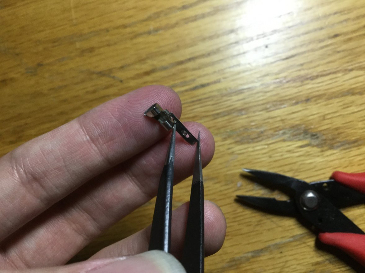
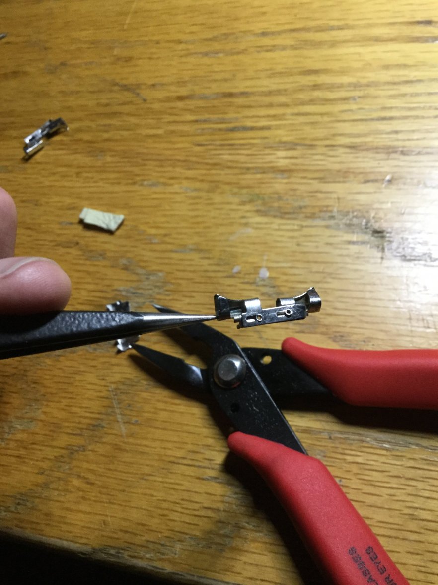
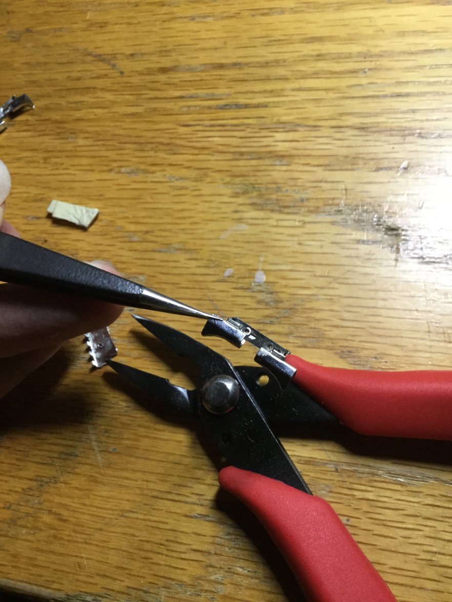
The method I used was to push and wiggle by inserting tweezers into the connector like this.
But, a lot more forcefully. The picture is just like that because I had to grow an extra arm for the moment of taking the picture.
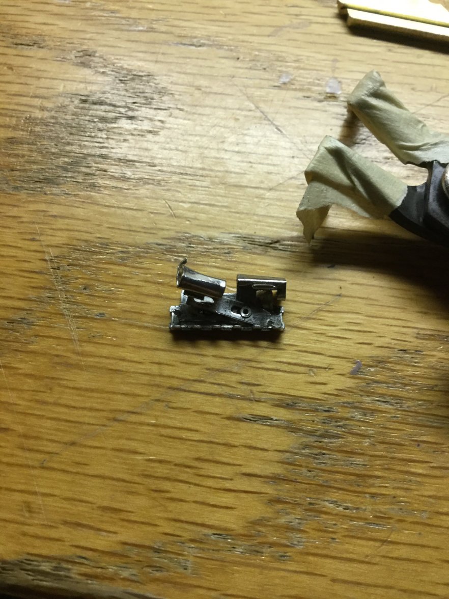
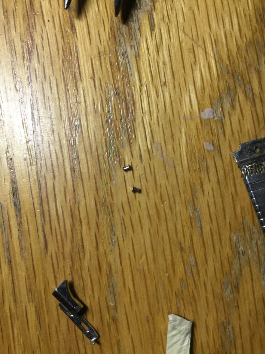
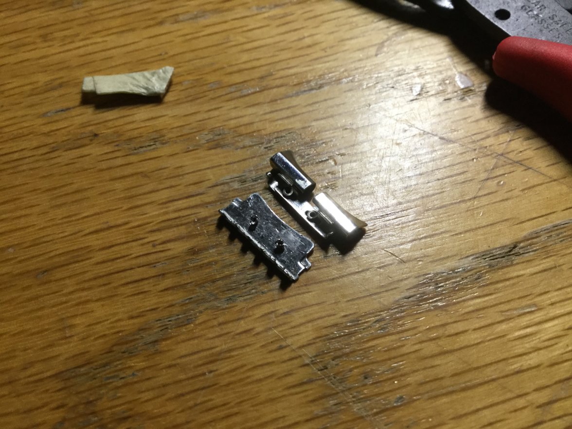
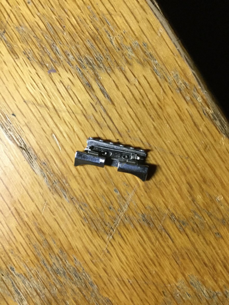
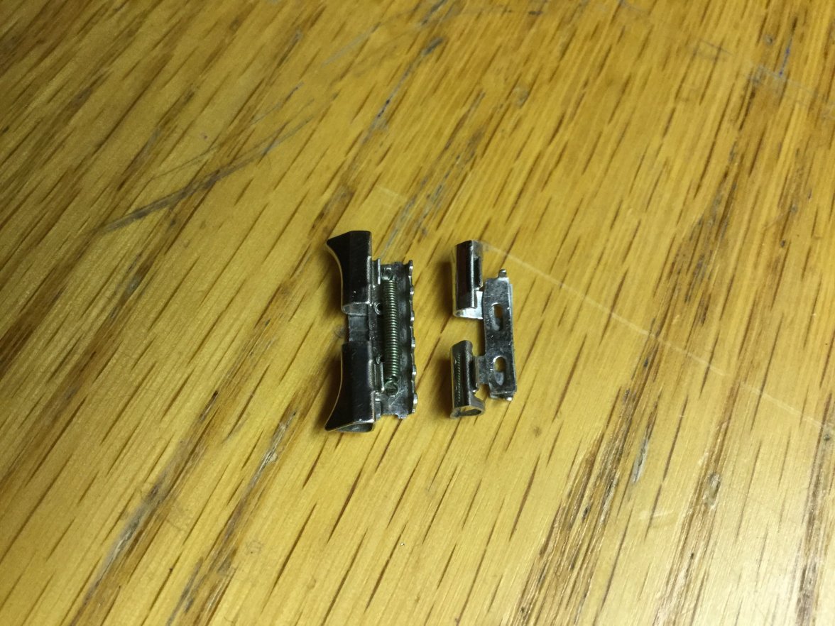
Now removing the connector from the donor base gives us this:
That's how it looks like in more detail.
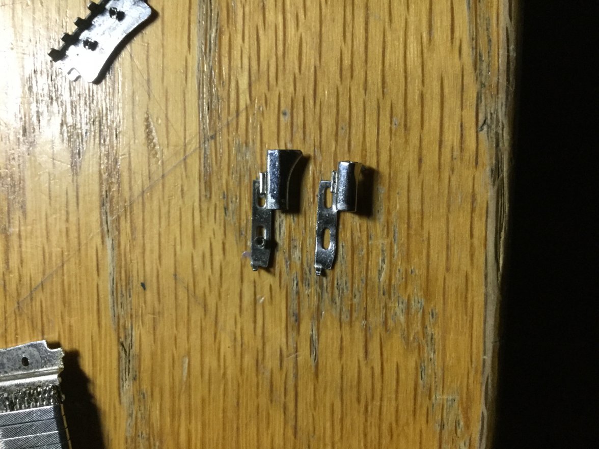
Push the connector further to fully separate the donor horns!
Notice how I had to bend the connector instead on the recipient base, because I didn't want to damage the bottom end of the connector.
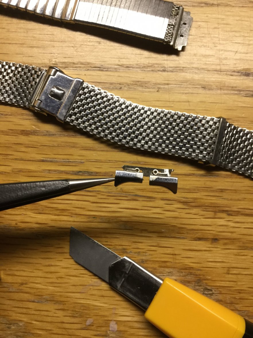
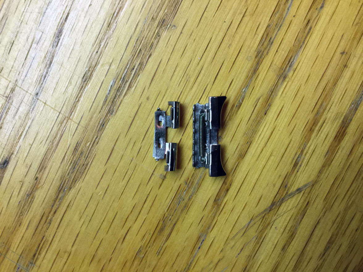
Side by side:
Great! You are now almost there.
Now you can mount the donor horn pieces on the recipient base. Wow!!! Getting more exciting!!
But you will notice the disc part of the I-connectors are bent. Well, you need to now flatten the disc heads to fasten the horn pieces. This was pretty hard for me. I guess it would be easier if I had a mini chisel or a mini hammer or something!
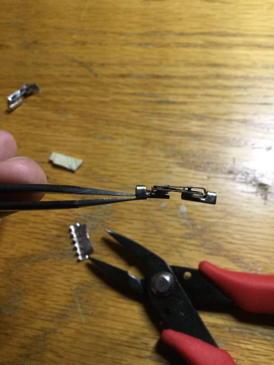
Mount the spring back....
Almost there!!!!
Now put back the top cover piece and make sure to clamp on both ends of the cover to secure it tight.
And now....finally!
🥰🥰🥰 The JB is back alive!!!
So that was the process I took. Hopefully this was helpful for you to fix your JB too, and in the very least, I hope you had some fun reading this long winded guide.
What is this guide worth if you don't have a JB to fix you ask? Well...I guess it's good reading to know how the JB works 📖 and also if anyone wants to convert a straight end piece to a horn piece this would be the way to do it...(Please don't ruin a perfectly fine one however. If you decide to switch end pieces, your I-connector will get pretty much trashed/beat up.) Apparently the horn pieces work best for 19mm and the straight pieces for 20mm anyway, so, live and let be all those JBs..!
I just finished restoring a sorry looking JB Champion that had its horn chopped off and twisted to its rightful glory. I don't know if this information will be of any use to anyone, but I thought I'd share in case someone had the same issue as me.
The bracelet in question, looked like this. Oww.....
Honestly this would have been a really easy fix only if that horn piece wasn't trimmed. Because the piece is trimmed, we have to replace the entire thing.
The bracelet on the bottom is the donor bracelet. It valiantly gave its life to save its more expensive brother.
I sat down at 10pm, and I remember lifting my butt off the chair at 4am. So after 6 hours here's what happened...
Perfect! Very happy with the result.
So here's the process. To successfully dismantle this thing, we have to understand the anatomy of the bracelet. I have been reading @TLIGuy 's excellent posts about the bracelets and that's where I got most of my structural background knowledge before actually handling one in person.
Here is the patent for the bracelet that @TLIGuy also posted before here.
This is quite confusing, but as we go through the guide you will see how the parts work and correspond to this diagram. This diagram will also be helpful for me to refer to the things you will see in the picture. You will notice that the bracelet at hand does not fully match the diagram as well - so keep that in mind.
Anyway the first step is to pry off what looks like to be piece 96, or what I will call the top cover piece. I followed the steps outlined here by @Stuie. (Great guide by the way if you want to shorten your JB)


(Pic reproduced here for convenience. Original pic of @Stuie. Forgot to take pics of disassembly)
So the first part to the left is piece 96, aka top cover piece. The piece to the middle is the spring/lug assembly, what looks like to be consisted of piece 50, 66, 64, 80, and 74. Here is what that middle piece looks like in detail.
I removed the donor's top cover piece first to check out the mechanism. Behold it in action!
You can see that there are two pieces of horn (part 64 and.. 66?) that move side to side and expand using the spring (part 80) inbetween. You can also tell that something was wrong with the way the unfixed JB on the bottom was. Probably technically the mechanism isn't broke but it's hard to show it expanding and contracting since the horns were cut.
So here is the problem statement.
The one on the bottom left is the twisted part of the unfixed JB. The one on the bottom right, is the better of the two ends of the unfixed JB. However both are trimmed, so the horns need to be transplanted from the one on the top.
First we take out the spring. You can slide it out with whatever tool you wish. But make sure it doesn't go PING! and fly across the room!
If you zoom in you can see how the connector bit of the spring is latching onto the two horn pieces.
So with the spring out how does the module look?
It looks like that, on the donor band. But here's the tricky part. The I-shaped connector (infamous part 74) connects the base (part 50) shown at the top, and the two horn pieces together. You can see the base still has the connectors. Normally only two connectors are used for the whole piece. (So that means I have two other horn pieces with no I-connector inserted between them elsewhere.)
The part removed from the band looks like this.
So now the problem is to find a way to remove the two horn pieces from the base. You need to keep the original base, because the donor base doesn't fit the mesh.
First I tried to bend the horn pieces to find an angle to wiggle the pieces out.
It turned out to be very ugly. I went with the first attempt because the trimmed horn pieces didn't matter much, but I knew for sure when I am going to remove the donor pieces I am not going to afford to do this.
So then I needed to find a different method, and wondered if I can pop off the I-connector.
However, I looked through my 15x loupe and found that the I-connector is a single piece, whereas I expected it to be a combination of two top and bottom pieces. (How did the factory get it to fit in the first place? Mysteries...)
So, I determined I need to bend the edges of the I-connector somehow.
This connector is a PAIN to deal with if you don't have the appropriate tools.
It is tiny, and you need small-tipped pliers for is. I tried using my tweezers and nearly destroyed the tweezers and slightly damaged the connector. Please get the right tools and save yourself the time and save the parts from damage. Please.
You can see the I-connector has two edges on top and bottom (hence why I call it an I, except with base on top and bottom). But one edge, on the bottom of the base (part 50) is slightly curved and more delicate than the other side of the connector that you can observe on the pictures above. The other side of the connector (top side) has more of a flat disc attached to the cylindrical connector body.
I had the option to bend either side, but I determined that I should bend the top (i.e. disc-shaped) because the bottom side is more delicate and hard to put back into shape. Also, it is the part of the connector that is exposed and touches the wrist, while the top side spends its life inside the shelter of top cover piece and two horn pieces.
However, I found that when I am trying to disassemble the donor modules, it is much more safer and convenient to remove from the base side instead, because there was no space for me to insert the pliers to bend the disc part and I did not want anything at all to happen to the donor horn pieces.
The method I used was to push and wiggle by inserting tweezers into the connector like this.
But, a lot more forcefully. The picture is just like that because I had to grow an extra arm for the moment of taking the picture.
Now removing the connector from the donor base gives us this:
That's how it looks like in more detail.
Push the connector further to fully separate the donor horns!
Notice how I had to bend the connector instead on the recipient base, because I didn't want to damage the bottom end of the connector.
Side by side:
Great! You are now almost there.
Now you can mount the donor horn pieces on the recipient base. Wow!!! Getting more exciting!!
But you will notice the disc part of the I-connectors are bent. Well, you need to now flatten the disc heads to fasten the horn pieces. This was pretty hard for me. I guess it would be easier if I had a mini chisel or a mini hammer or something!
Mount the spring back....
Almost there!!!!
Now put back the top cover piece and make sure to clamp on both ends of the cover to secure it tight.
And now....finally!
🥰🥰🥰 The JB is back alive!!!

So that was the process I took. Hopefully this was helpful for you to fix your JB too, and in the very least, I hope you had some fun reading this long winded guide.
What is this guide worth if you don't have a JB to fix you ask? Well...I guess it's good reading to know how the JB works 📖 and also if anyone wants to convert a straight end piece to a horn piece this would be the way to do it...(Please don't ruin a perfectly fine one however. If you decide to switch end pieces, your I-connector will get pretty much trashed/beat up.) Apparently the horn pieces work best for 19mm and the straight pieces for 20mm anyway, so, live and let be all those JBs..!

