JimInOz
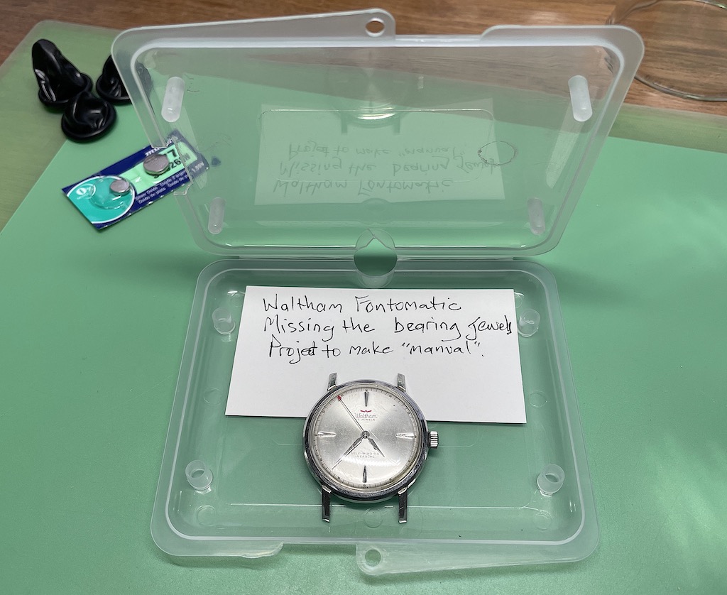
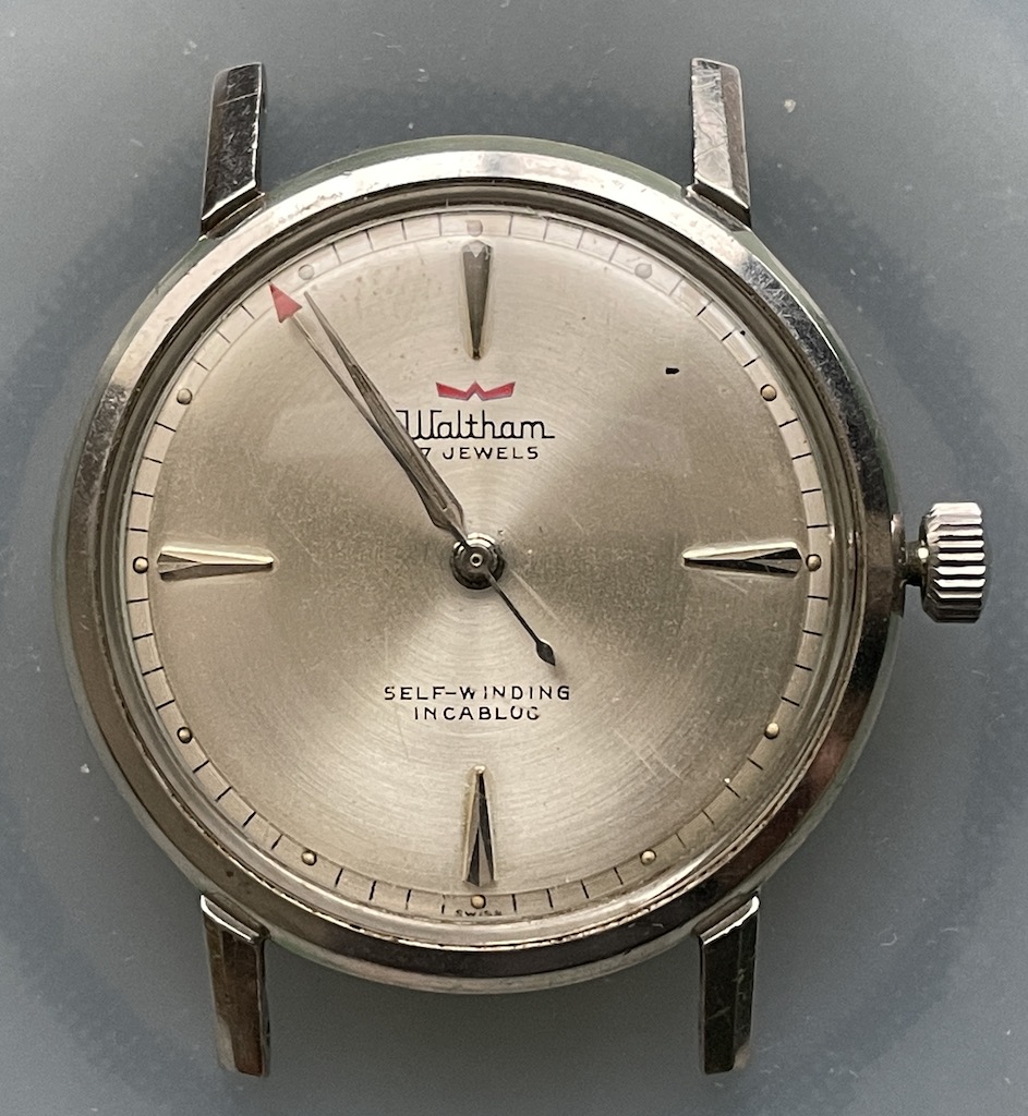
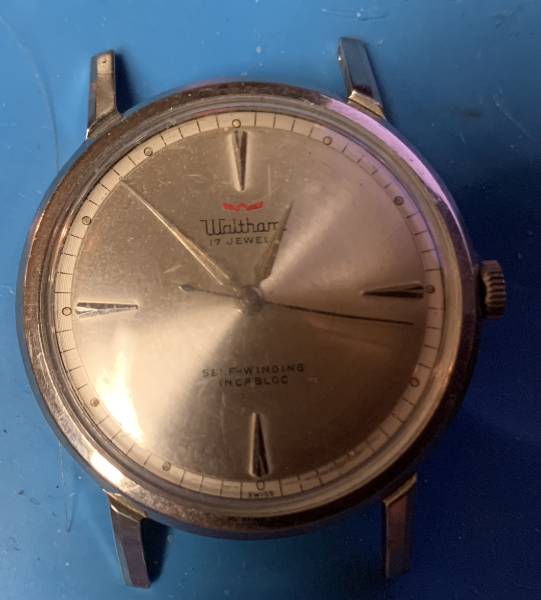
··Melbourne AustraliaSome time ago, one of our members found a Waltham automatic he'd picked up at a garage sale. Following some intervention by @STANDY, the little Waltham ended up in my project drawer.
And there it rested, alone and forgotten.
Now, 678 days later it has made it to the bench.
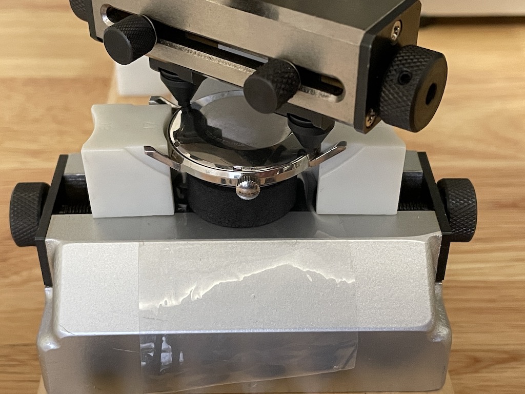
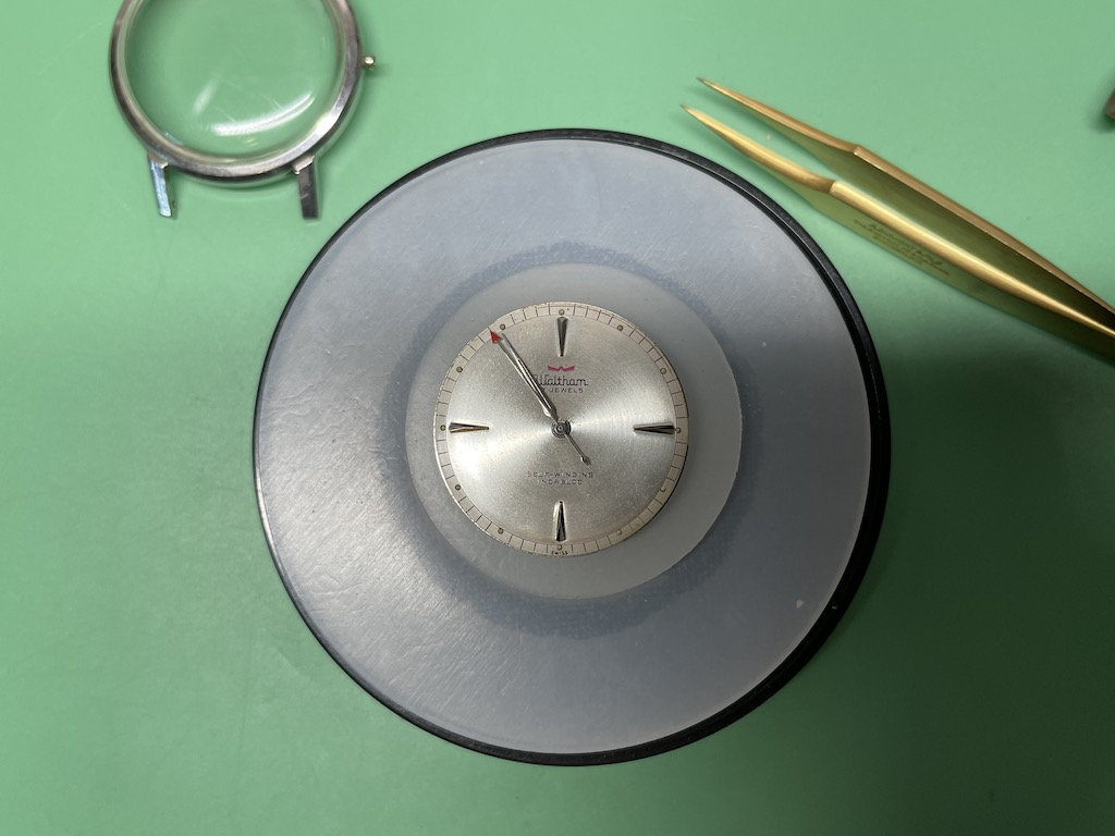
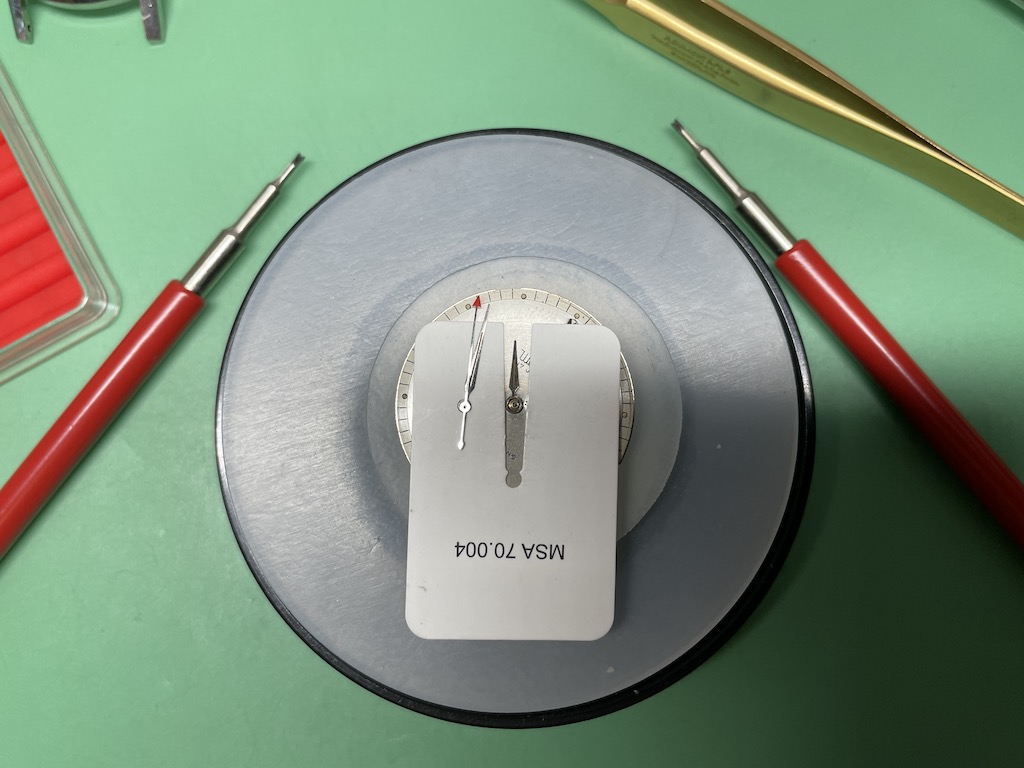
First thing is to align the hands for removal.
And then open it up.
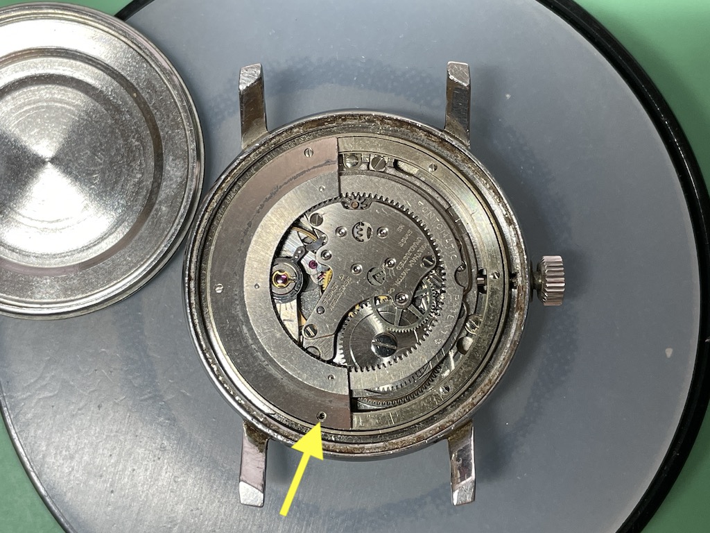
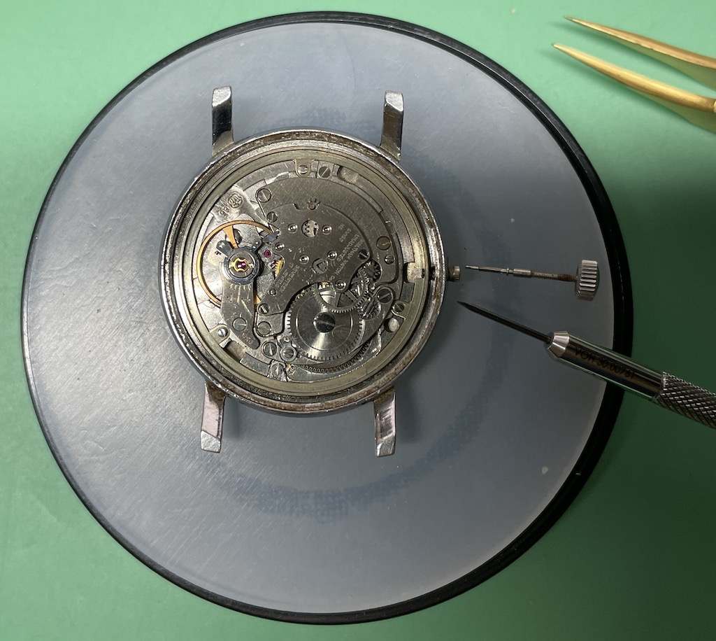
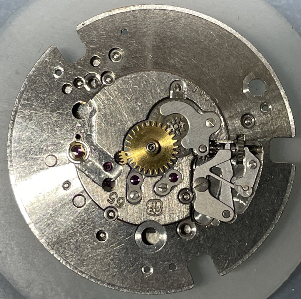
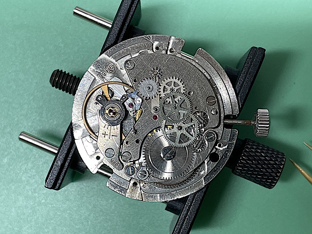
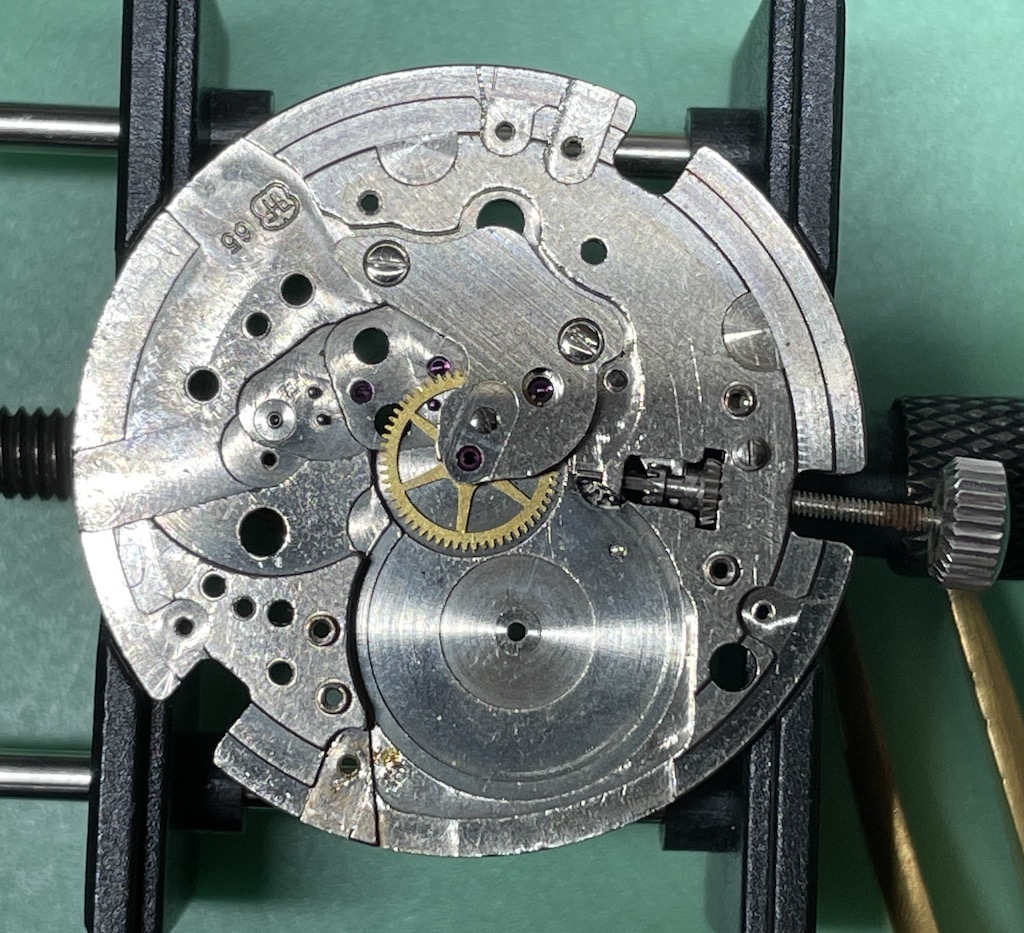
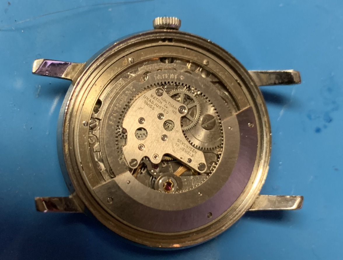
Now that it's open we can see the movement. An FHF 95-4 with an unusual "peripheral rotor".
We can already see that one of the rotor group screws is missing.
The rotor was able to be lifted straight out, which isn't normal. However, if it's missing the rotor bearings (72 of them) it makes it very easy.
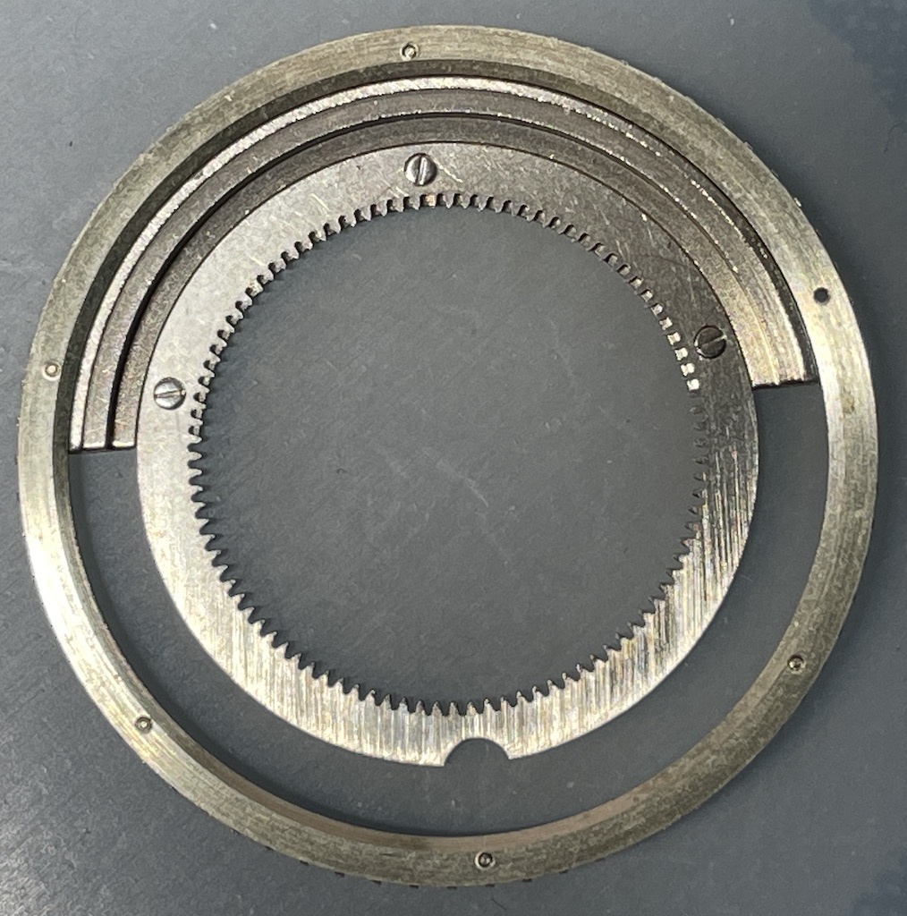
We can see on the underside of the rotor that there are no bearings peeping out from the edge of the rotor ring.
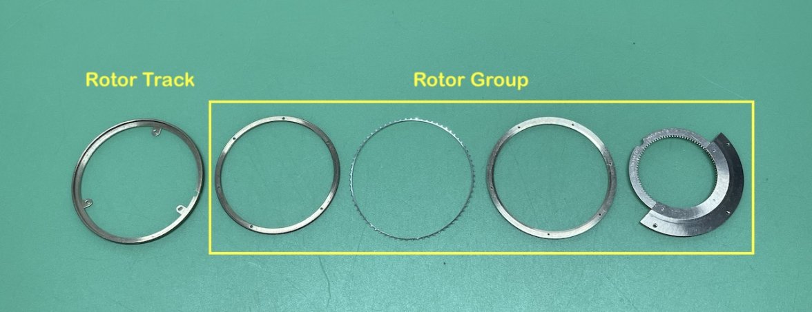
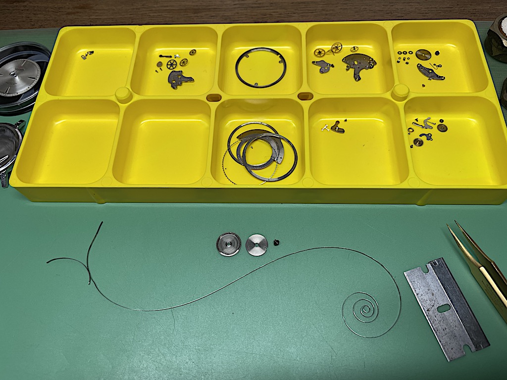
Here is the breakdown of the automatic rotor, the "rotor group" parts are assembled into the rotor track in sequence from right to left. As I see it, the first ring is placed in the track, then the bearing cage, then 72 ball bearings are dropped in, then the next ring is fitted and screwed down, finally the rotor weight is fitted and screwed down. I think it has to be done in-situ as the three tabs that hold the assembly to the movement are covered by the assembled rotor. The whole rotor group is held in the rotor track by the bearings protruding into an angular groove or race in the bearing track.
EDIT: Even with the picture in front of me I couldn't see it 🤦. The rotor has a cutout opposite the weight, this allows you to access the tab screws for the rotor assembly which can be removed in one piece after the three screws are removed.
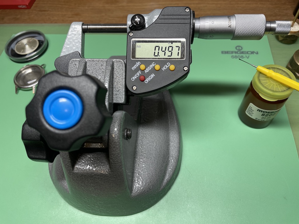
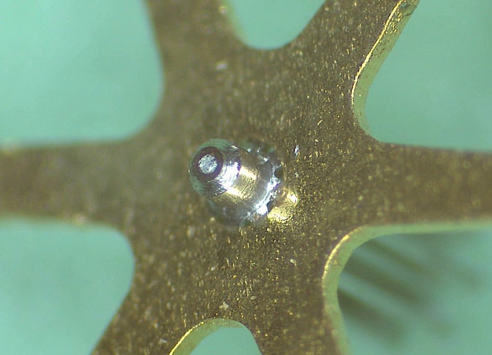
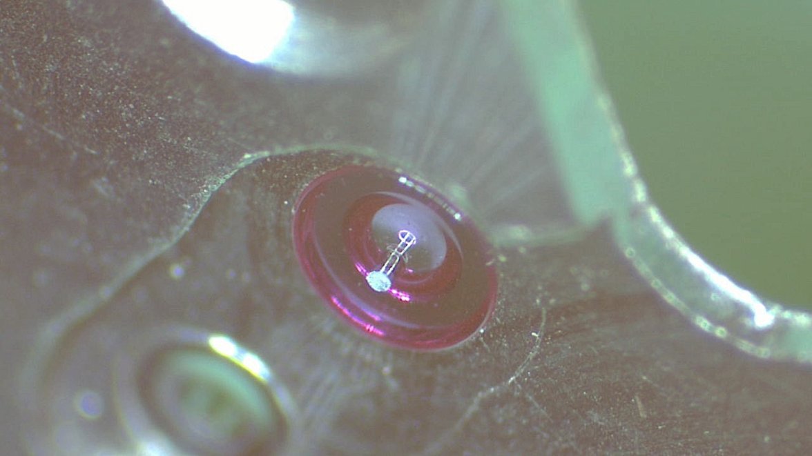
The bearings are extremely small, I measured the one I found by placing a spot of grease on the anvil of a micrometer, then used an oiler to place the bearing on the anvil so that I could measure it.
So unless I can find seventy one 0.5mm ball bearings (one fell out of the movement later) the chances of having an operational rotor are looking slim.
Edited:
