Bringing a Smiths car clock to life

Posts
306
Likes
523
Your very welcome Chris.

The diode is used on all relays in aircraft and it does a great job of preventing the collapsing reverse magnetic field from the coil sparking across the contact gap and causing pitting/wear, or feeding back in the circuit, installing a diode should help in your application.

vinn2, the diode should work in any application with a coil/electromagnet field that collapses and discharges it's voltage back into the circuit or across a set of points.
Edited:
 
Posts
2,219
Likes
4,945
This is very interesting as I don't do much electronic design so I'm having to think it through (hopefully correctly). I'm going to get a bit technical and see if you think I'm on a good path.

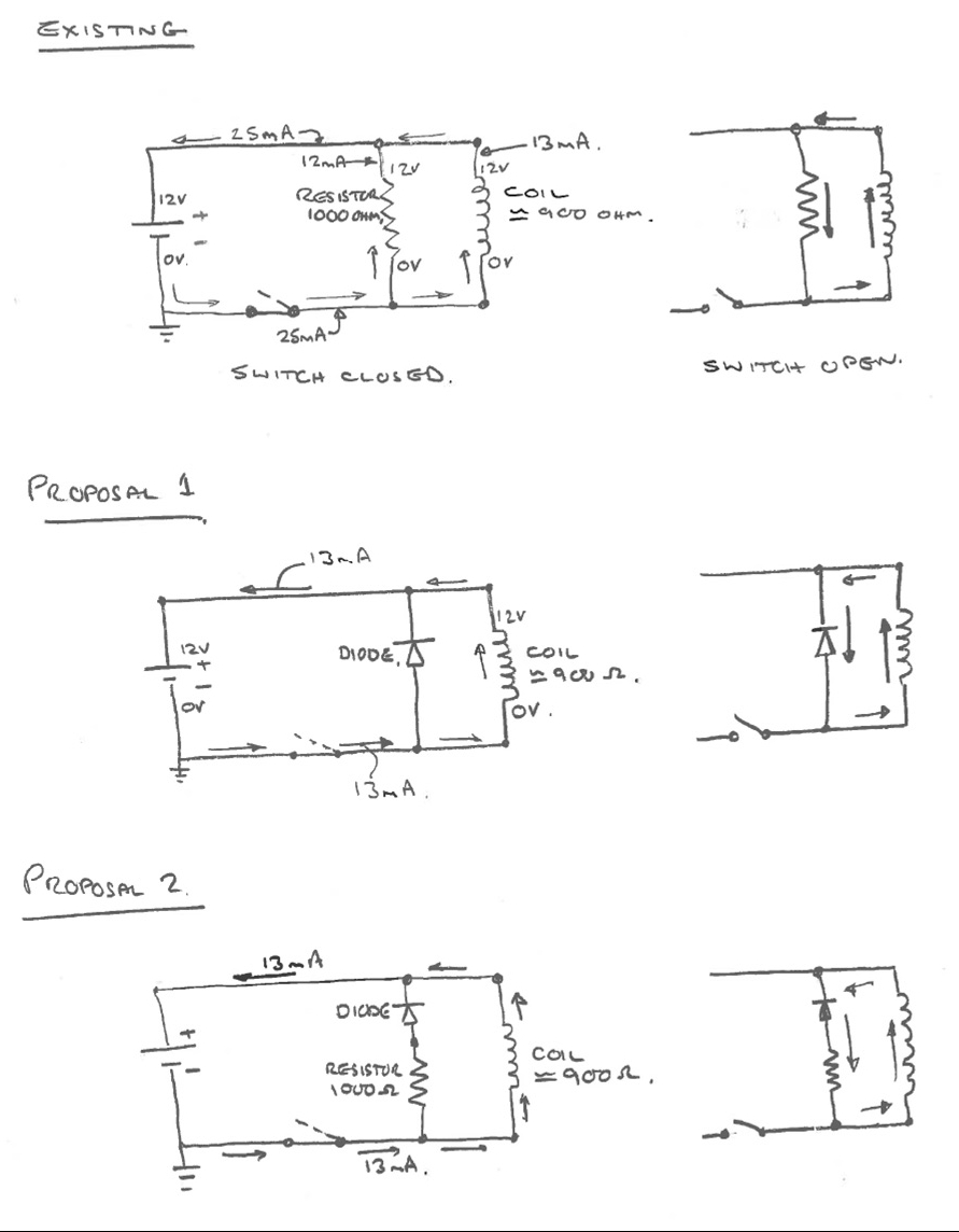
This business of adding a diode is not as simple as I thought. Today, I have the first circuit below. When the switch is opened and the magnetic field in the coil collapses, it introduces a voltage spike in the circuit and without the resistor leg, it will lead to high voltages at the switch contacts (my pin and prong) which causes arcing. Today, there is a resistor in parallel with the coil so that as that voltage spike is generated, it has a path away from the contacts. This is likely working fine but, it does mean that the current away from the coil is 25 mA for a coil current of 13 mA. Without the resistor, the circuit would run at 13mA when the switch is closed so, the contacts are seeing a higher current than they need to (and they are pretty poor contacts anyway).

Proposal 1 is based on Robs comments which make good sense to me. This has halved the current at the points which is a good thing. When the switch is opened, the voltage spike flows back through the diode leg and protects the contacts. The only problem I see with this is that the collapse time for the coil flux will increase as the resistance of the diode when it is working is very low. It may be that the field may not have collapsed completely by the time the contacts close again. Probably not a good thing. This is the difference from a relay where they are not usually being used in on-off fashions very rapidly so, the field collapse time is not so important.

Proposal 2 is as Proposal 1 but, with an added resistor so, the coil field should collapse rapidly. For this particular application I think, Rob this will work better. Thoughts?


First is to get it running with the existing configuration and put it on a scope to confirm that I have this correct and then introduce the diode.

Cheers, Chris
 
Posts
306
Likes
523
Hi Chris,

Proposal 1 is the standard set up with the diode reverse biased against the applied voltage. Only a small correction to the switch open circuit, the back EMF travels the opposite direction of the applied EMF, not in the same direction as you have drawn, the back EMF is why the diode does it's job in short ciruiting the voltage from the collapsing coil magnetic field.

I would expect the diode to shunt the voltage very quickly after power is removed, as soon as the diode is forward biased and conducts, the internal resistance is virtually zero.

I suspect that the shunting should happen quicker than the oscillations of the balance wheel, in any event even if they don't as the circuit was originally there was sparking and erosion of the post, with the addition of the diode the amount of residual voltage has to be reduced significantly and as a result the sparking and erosion should be reduced by a large margin.

Interesting to see the scope results.
 
Posts
16,990
Likes
156,371
I seriously doubt that such information is available on any other watch forum.
Thanks guys, I love it and openly admit that much of it goes way over my head 👍👍👎
 
Posts
2,219
Likes
4,945
Hi Chris,

Only a small correction to the switch open circuit, the back EMF travels the opposite direction of the applied EMF, not in the same direction as you have drawn, the back EMF is why the diode does it's job in short ciruiting the voltage from the collapsing coil magnetic field.

You Electronics Engineers and your confusing sign conventions. 😉 Yes, I know what is happening but now I look at my schematics... At least I have the idea right👍

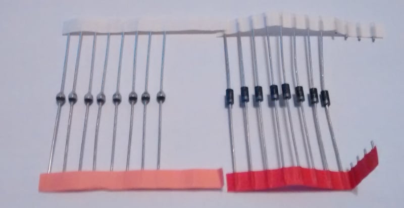
Parts box yielded only two diodes which I will look up the specs for, BYT52MV on the left, which I'm pretty certain are power rectifier diodes and IN4007 on the right for which I can't remember the usage at the moment. Pretty sure that either would be alright here but probably the IN4007 as the BYT are avalanche type. There must be at least ten types of diode and I would imagine choosing one is not easy - mostly, I just replace like with like!


I seriously doubt that such information is available on any other watch forum.

I don't think anyone else would be bothered with such involved discussions😀

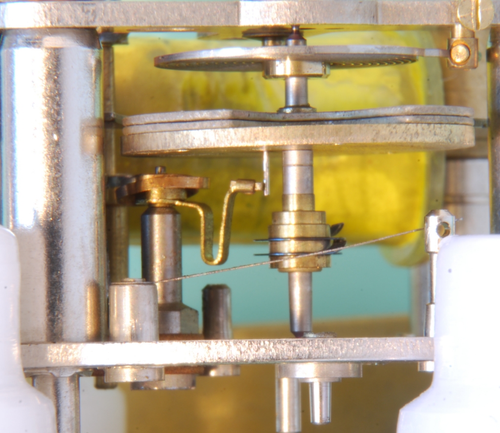
Put the balance back in and tweaked everything so the prong works on an unworn part of the pin as I can't find anything suitable to replace it.


The balance settles with the pin and prong in contact which I'm not sure about as there is a different starting mechanism. Anyway, will put it together and try it. It makes a reassuring click-click when the balance swings now this is back in.

Cheers, Chris
 
Posts
568
Likes
1,260
Ah who cares about the other forums. I love posts like these! Keep us posted! 👍
 
Posts
306
Likes
523
Morning Chris,

Understood on the current flow, naturally you indicated the path of the holes, not the electrons...happens all the time... 😀

I think the 1N4007 is a good choice for the application, it's simply acting as a low power shunt and should be fine.

Re the pin itself, if you think you are able to press it out of the balance and press in a new one, I am sure I can make a replacement. If I made the new pin in high carbon steel and left the acting tip dead hard, maybe it wouldn't wear as fast? I will gladly do this no charge, it's only a few minutes to turn it on the lathe, let me know on PM if I can help.

Interesting to find out how it runs after the overhaul.

Rob
 
Posts
2,219
Likes
4,945
Re the pin itself, if you think you are able to press it out of the balance and press in a new one, I am sure I can make a replacement. If I made the new pin in high carbon steel and left the acting tip dead hard, maybe it wouldn't wear as fast? I will gladly do this no charge, it's only a few minutes to turn it on the lathe, let me know on PM if I can help.

Thanks for the offer, Rob. That's very kind. The issue with pressing it out is that I would need to remove the permanent magnets to get to the back of the pin. Then it should be easy. Unfortunately those magnets appear to be glued so it's not a quick job and I risk damaging the balance. I'll try it as is for the moment but may come back to you👍

Will get those scope pictures up when it's running this weekend. Base movement is now assembled and is running freely. Al, you were right those worm gears are about as cheap as you could make. Why Smiths suddenly went south is a bit of a mystery as it appears to be before the quartz revolution and hit all their divisions yet they clearly had worked hard to keep costs down. They limped on for years but at nothing like their business level in the 50s and 60s.

Cheers, Chris
 
Posts
306
Likes
523
Hi Chris,

Understood on all points.

If the pin is quite worn and changing it is too risky, maybe the fabrication and installation of a tube over the pin may be a solution.

Regarding Smiths I worked on a number of aircraft over the years with Smiths Avionics systems, autopilots, instruments etc...they sure made a large variety of items over the years.

Rob
 
Posts
441
Likes
65
do you know what year the clock was made? or how many cars had the same clock movment?
 
Posts
2,219
Likes
4,945
My car is a 1963 so that dates the clock. Certainly, Jaguar used them for all Series 1 E-Types and likely Series 2. They also used them in other models and, I would imagine, other companies used them as well. In the Series 1 parts list, they are listed under the Smiths part number. I have a similar clock in my much earlier 120 so you're probably looking at 100-200 thousand just for Jaguar. So, likely a half a million were made.

The clock runs 😀 now (well the balance does)

I had to join YouTube to do this so, hope it works. My phone won't pick up the sound so will have to get more serious....

I pulled the train as the amplitude was poor with it in (45-50 degrees) but the balance on it's own is showing 150 degrees or so. I think a little tweaking is in order as I may have the balance Endshake too tight. The way the balance drives the first wheel is quite odd and I think it needs to float more axially. We'll see - first set up the electrical side and then add the wheels checking for amplitude loss. I'm a bit in the unknown here as it us not a typical movement. Currently happy running under a large Tupperware carton.

Will get the scope out tomorrow.

Cheers, Chris
 
Posts
2,219
Likes
4,945
So, some scope pics. I don't have the best of scopes (€300 Chinese not a €10000 Tektronix) but it works well for the sort of thing I usually use it for, which is all hi-fi and amplifiers. This is such a long time base as it's running at about 2-2.5Hz and no audio gear works down there. Quicker than I thought and is not far off a 565 which runs at 2.75 Hz. Anyway, we won't be getting that sort of accuracy!

Here it is with the existing circuit. I'm measuring the voltage at the bottom of the resistor leg in the above photos.
The pulse is the lower line and is 12V then there is the huge spike in reverse going upwards which it may be possible to see peaks at about 18V. This what Rob is trying to avoid with the diode. According to my Multimeter, average current consumption is 4mA.

Next, I cut out the resistor and added the 1N4007 diode in it's place (Proposal 1 above). The 12V pulse is still there but the upwards undesirable flux collapse pulse is almost completely removed and peaks at about 2V. Now, average current consumption is 2mA as we're no longer driving the resistor all the time. This may not sound much but, this it all helps to keep the battery good in the car when it's left standing.

My concern here was the drop off of the coil collapse current but Rob was sure it would not be a problem. Here is the same as above but with a longer time base to show two pulses. It's clear that the flux collapse effect is dying off almost instantly and far before the next pulse. This just confirms what Rob always knew...

I learnt a little more today so, it's a good day😀.
Just need to put the train back in and see if I can make it maintain it's current 160 degree amplitude. It's never going to be that huge as unlike a watch, the balance is actually driving the train.

Cheers, Chris
 
Posts
306
Likes
523
Well done, excellent results and I am sure your wear sparking issue will not be a concern any more. Looking forward to the train install and final results.

Rob
 
Posts
2,219
Likes
4,945
I'm happy with the electronic side now, thanks so back to a watchmaking issue....

Installed the train up to the cannon pinion and no major drop in amplitude, perhaps 10-20 degrees. Remembering that this is the power source of the train, this is pretty good.

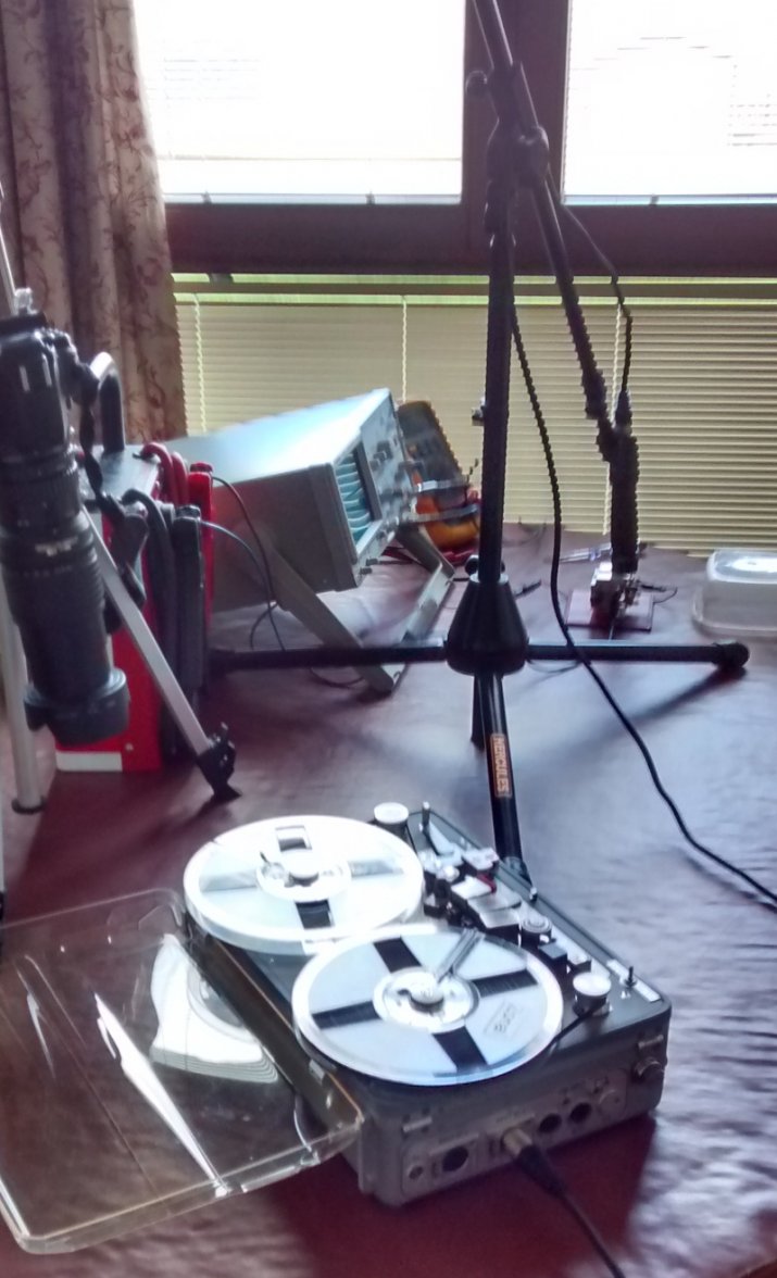
You can't hear the movement in that clip so, I used my old Nagra and an SM57 microphone. Then played it back through the Nagra monitor speaker to get it on my phone in a low quality mode. I'm working on the dining table here as I have a lot of kit in play. The clock is next to the Tupperware box.


It turns out you can't upload just audio to YouTube so, downloaded more Android software to make a video to upload which includes some random scrap phone photos from the Goodwood Revival 2015.

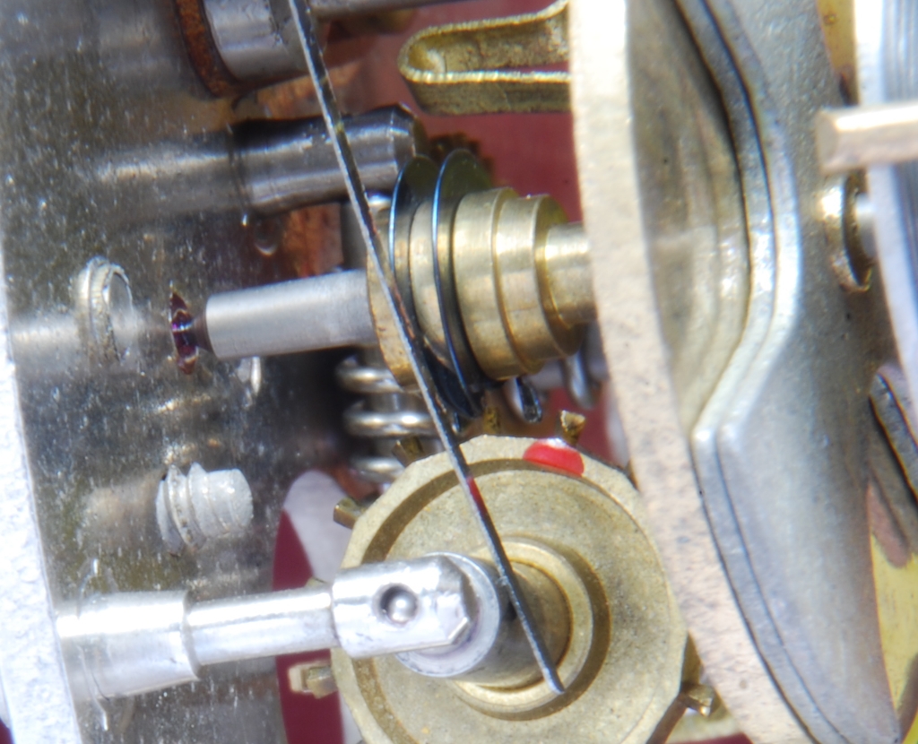
Anyway, what you're hearing is the interaction of the balance wheel with the first wheel and every revolution of that first wheel, there is a loud thump as the balance wheel tries to drive one tooth. In fact, sometimes it fails and jams so the movement stops.

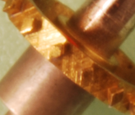
It's the one with the red mark here. The two black sheet steel rings on the balance slide between these teeth to transmit the drive. They're shaped to do that.


Have tried moving the whole balance in both directions plus varying it's Endshake and can't solve it so, the only option is to dress this one tooth as it's out of spec. I think this is why there is no real pivot wear, it has never run correctly. The tooth is nice and bright in one area so, at least I know what's hitting.

Ah well, that's for another day. That little job of cleaning, oiling and regulating just keeps expanding....

Cheers, Chris
Edited:
 
Posts
2,219
Likes
4,945
So, that tooth was just damaged. Looking here, it should be a rhombus shape like the others but, it has been flattened at the upper edge.

I dressed it with the smallest file I have. Luckily, this shape is not that critical and this is hardly the sort of precise work Rob showed with that Ladies watch balance staff. Now it runs fine and reliably and has settled down after five days continuous running.

Put it on the timegrapher and adjusted the rate to give a more or less horizontal line (line is too strong a word as it a lot of points scattered about a mean). Anyway, here it is on a little phone analysis tool called Wildspectra.


It's showing as a 2.5 Hz (18000 A/h) beat with an averaged rate over a minute of +33 seconds per day (red). The other two are 20 second and 5 second averages and there's a lot of variability in the blue, 5 second average. Anyway, if it runs within a minute a day, I'll be very pleased!

Cheers, Chris
 
Posts
2,219
Likes
4,945
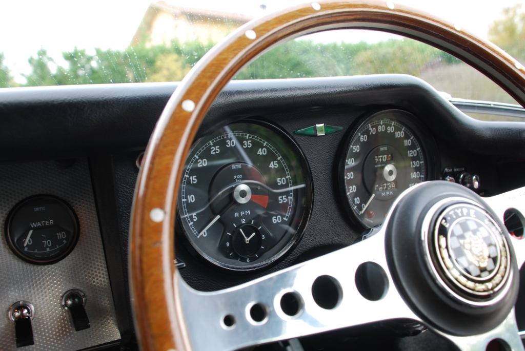
And finally back in the car. 😀


Sprayed the dial and hands and there was no way to keep the numbers but, thanks to all for the suggestions. It's a real pain to fit as there is so little access so I had it running on the bench for 8 or 10 days. I chose an off white for the hands to simulate some age but could have used brilliant white now I see it fitted. Ah well.

I was most unfair to the original Designers above when I mentioned I'd be happy if it was within a minute a day. It's within 30 seconds after the bench test (there is no second hand so that's the best I can measure). This is under 4 seconds per day so that's chronometer spec, although one position only. Runs in 5 positions (to simulate cornering, acceleration and braking) but not so good in 6H. Anyway, if it ends up in 6H, I'll have more on my mind than the accuracy of the clock...

Cheers, Chris
 
Posts
7,225
Likes
24,420
Nice job Chris, oh and any gratuitous pictures of your car are always welcome.👍