Forums Latest Members

Exam results 2017! Watchmaking with the BHI

  1. Archer Omega Qualified Watchmaker Aug 24, 2016

    Posts
    26,671
    Likes
    66,235
    Nice summary Chris. :thumbsup:

    François,

    I'll answer some of your questions...

    I'm not 100% sure what item you are asking me is true. Is it true that Rolex doesn't dynamically poise? I have no idea, but if they didn't I would be surprised. Any free sprung balance that has weights on it for timing adjustment (like the Microstella that Rolex uses, or the Gyromax that Patek uses, or the square and other screws that Omega uses) will potentially affect poise when they are moved for regulation purposes. This is why regulating these watches is not something for the inexperienced to do - it's not like turning a regulation screw on a base ETA movement. So in a way you could argue that any time someone moves one screw a little more than the one opposite and creates an error, then works to fix it, they are dynamically poising the balance.

    I've never seen an explicit declaration from Rolex saying they don't do this, or that trained watchmakers are not allowed to do this when servicing a Rolex. Not sure where this information comes from, so it doesn't sound particularly legit to me.

    Dynamic poising can have detrimental effects, in particular if not done right, which is why it's not something you likely should be doing right now. If you are working on a watch that has a smooth balance with no screws, it requires removing material from the balance, and this is not reversible. If too much weight is removed chasing an error, then you risk problems certainly (affecting Q). It can affect amplitude in ways you might not expect, and of course as amplitude changes, timing changes.

    But keep in mind this is usually something done for very fine adjustment, not normally for gross adjustments. So the amount of material being removed here is VERY small. So taking a watch from this:

    [​IMG]

    To this:

    [​IMG]

    Only requires removing this:

    [​IMG]

    The watch was well within specs when I started (Omega allows 12 seconds of Delta over 5 positions and I started with 8.5 over 6 positions), but seeing a poise error that would be easily reduced, I went ahead and corrected it.

    Short answer is - physics! :D If you want send me your address and I'll dig up my old dynamics textbooks from college and send them to you - I haven't used them in 30+ years so I'm not going to try to explain it in detail here. ;)

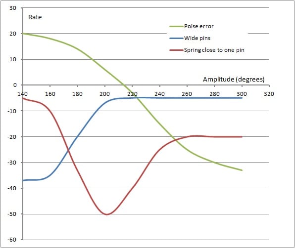
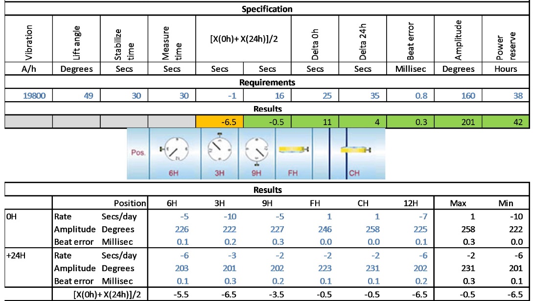
    You can see the affect of amplitude on various parameters in the chart Chris posted above. In the case of dynamic poising, I was taught to use 160 degrees of amplitude, as this magnifies errors to make them more easily seen. But you need to understand the amplitude point where the errors flip, so if you want to use a high amplitude you can, just understand the implications of doing that when you decide where to remove material (or add it if possible) on the balance.

    When you can make balance springs perfect in the round and in the flat, adjust the regulating pins to minimize Delta, and ensure that all other issues are resolved, then we can talk about doing dynamic poising. Based on what you have written, I don't think you are there yet. I would be interested to see a balance spring photo (static) that you have corrected - this usually tells me how far along someone is.

    I recall posting a spring once on a forum that was a long way from being centered, and some people commented that they could not see the error really - looked fine to them. It's not that I have any special ability built into my eyes at birth, but just that I have seen and corrected enough errors that you learn to recognize what is good and what isn't. What might look great to you will most likely not look so to me, but I have looked at and corrected thousands of springs - there is no short cut to learning this stuff as it takes time and experience.

    Cheers, Al
     
  2. François Pépin Aug 24, 2016

    Posts
    1,531
    Likes
    1,083
    Thanks a lot Chris! I really appreciate.

    I already knew and use most of your tips. But you made all that very clear and show me I have to increase the precision of my work. Reading your very clear sum up of these steps underlines that I have to do better what I already (try to) do. Thanks!

    However, I will not be able right now to check the parts with a microscope - I do not have one and can only do that with my x 16 lens.

    The part concerning the dynamic poising and the different changes the amplitude causes is new for me. Really interesting! I will stuff that closely. If you have other graphes like that, I would really be happy to see them.

    That´s what I like with good forums and nice people: you always learn interesting stuff - and see that you have to improve!
     
    Edited Aug 24, 2016
  3. ChrisN Aug 24, 2016

    Posts
    2,218
    Likes
    4,760
    I can see you've definitely got the bug. It's frustrating in parts and then there are the good days when you just get everything right:D and it all goes together smoothly and any problems leap out at you... OK, they may be few and far between but eventually they get more frequent.

    I'm doing most oiling now under the microscope (another idea from Al) as it gives me greater precision. It's taken me some time to get used to this but I would recommend it even if at first there are a lot of false starts. I didn't think this would be for me but I now hardly use anything other than a 3 times eyeglass and then the microscope.

    The guys here and in particular Al, have always been encouraging even when I've shown stuff that was not good so don't be afraid to share your errors and what you think is good. It's not the main purpose of the forum but we're an accommodating group and you won't see the sort of detailed responses Al posts anywhere else that I'm aware of. As he mentions above, what might seem good is not necessarily right to someone with a lot of experience.

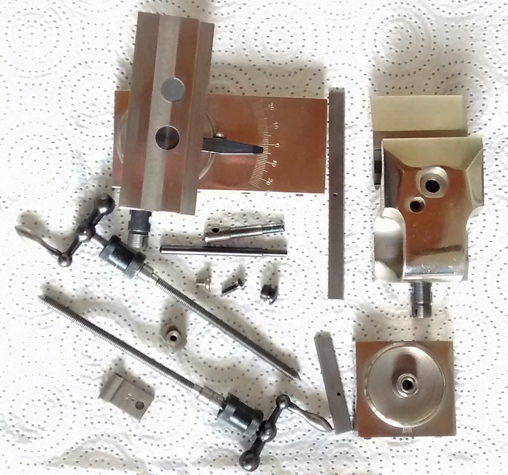
    Now, today I've fired this up for the first time... it's a whole new thing for me. Here, some parts disassembled for cleaning. Obvious to me what it is and I suspect to all the other Watchmakers and tinkerers but, I think it's a very cool thing to have - every Engineer should keep one in the house even if just to look at! Some of the guys in my current day job are very jealous.

    And when I'm sad - I slide.jpg

    Cheers, Chris
     
  4. François Pépin Aug 24, 2016

    Posts
    1,531
    Likes
    1,083
    Awsome Al! Thank you very much!


    You are right: I do not think I am ready for the dynamic poising. But I will certainly try some day because it is really interesting. My aim is not really to improve the accuracy of d'y watches - when I get a delta of 20 sec for a vintage I am happy, even less if it is a cheaper or a worn movement. But I want to understand this stuff and try to get, on some occasions, the best of a movement and of me!

    Actually, I was thinking of a particular wach when asking my first question. It is a JLC 481 (first automatic watch to have a power reserve complication). I have serviced it a few weeks ago, but was not satisfied by the delta (40 sec over 6 positions). I had noticed that the vertical positions were faster than the horizontal ones. So the solution seems simple: opening the pins, which actually were almost touching the spiral. And, as it is often the case with the old vintages I usually service, the spiral was not at all centered.

    So I opened the pins and tried to correct the position of the spiral. But when I tried to adjust the flatness, the spiral broke just before the stud. Maybe it was my fault, maybe it was already very worn, probably both! Whatever, I fitted again the spiral in the stud (I do not know the English word here - "repitonner" ou "regoupiller" in French). Then I framed a new last coil and adjusted the beat error - which obviously was not good at that point!

    Obviously, after this kind of issues and fixing (with my limited skills), I could not expect chronometer performance! But I was not at all happy with the new delta: 90 sec!

    At this point, I thought I should do some poising! It really improved the results as I have now again a delta of 40 sec. And I think I can do better by adjusting a pin because I have a pretty big difference between DU and DD. Chris made me understand I did wrong adjusting this pin at its end and not at its begining...

    But I was wondering why a JLC balance would be so unpoised - I had to add weight. And I thought I might have disturbed a dynamic poised balance when I accidently shortened the hairspring. Not sure of course. So I thought I could try to understand a little more dynamic poising...

    Actually, I am not going to try that now, and certainly not first on a JLC! If I want to get better results with this watch, I will rather check everything you (Al) and Chris have friendly pointed. Maybe I can also do better with my poising. I shall add that I choose not to change the mainspring because it was (like the) original, which has a special device that I thought I would keep.

    Al, I will certainly post some pics of some hairsprings I (tried to) correct. I would be happy to read your criticisms, remarks and advices. I am sure that was is good to me will not be good to your experienced eyes, and that could be a way for me to improve! Actually, I am afraid the pictures I will take (this week-end in order to do some thing as good as I can) will show some issues to my own eyes...

    Thanks again!
     
    Edited Aug 24, 2016
  5. François Pépin Aug 24, 2016

    Posts
    1,531
    Likes
    1,083
    Well, I have spent nights trying to correct a hairspring, so I guess I am really "atteint" like would say the French!

    Chris, thank you for you help and your support. I will certainly post pics of my "work".

    Actually, I do not know the tool you are cleaning. But I am not an engineer... (I teach philosophy - but I publish in the field of history and philosophy of science and technics, so maybe it is not so remote! And one of my current research field is history and philosophy - yes sire! - of watchmaking in 18th c France. But maybe that will be for another post later...).
     
    Edited Aug 24, 2016
  6. ChrisN Aug 24, 2016

    Posts
    2,218
    Likes
    4,760
    Sounds interesting.:thumbsup:

    Regards, Chris
     
  7. François Pépin Aug 25, 2016

    Posts
    1,531
    Likes
    1,083
  8. François Pépin Aug 25, 2016

    Posts
    1,531
    Likes
    1,083
    Hello Chris,

    I have thought about all the advices and explanations you and Al gave me. Thanks again!

    One of you tip could actually solve part of my delta issue with my JLC 481. I have other variations, but one that both et me is the DD versus DU (about 25 sec). I knew the pin should be parallele to the boot, which is currently not since I regulated it at the tip and bit at the root. I will try to correct that as soon as possible.

    But I cannot understand why a pin closer to the the boot at the tip should produce a DU faster than DD. Is the spiral not closer to the pins when the position is DD - because of the end shake of the balance pivots? Is that is the case, how a shorter gap between the pins could conduct to a slower rate (DD versus DU)?
     
  9. François Pépin Aug 25, 2016

    Posts
    1,531
    Likes
    1,083
    Thanks. I shall sum up one of my topics to catch your interest.

    In the Encyclopedie directed by Diderot and d'Alembert (1751-1772), the articles concerning watchmaking are written by important watchmakers of that period (such as Romilly and Berthoud) and deal with many subjects. They consider movement description (with very interesting "planches"), technics, practice and theory.

    One original idea is that watchmaking is the science of movement. It is not a simple assumption and, actually, almost every scientists and philosophers were already considering that Mechanics is the science of movement. But Romilly and Berthoud stated that watchmaking is the science of concrete movement, with a powerfull insight concerning tribology. One idea is that, unlike Mechanics, watchmaking considers movement not only through space and continuous time, but through rythm (my words).

    For instance, watchmaking frames original questions about "frottements": physics studies their causes and how they disturb a system, but watchmaking considers them as a key to understand the system. For a watchmaker like Romilly, watchmaking is the true science of frictions in relation to time.
     
  10. ChrisN Aug 25, 2016

    Posts
    2,218
    Likes
    4,760
    Hi Francois

    To be honest, the most likely cause of variation between DD and DU in my experience is an amplitude variation caused by a dirty jewel, one jewel over oiled, worn balance pivot as well as a host of other possibilities... excessive end shake of the balance or fork could be one thing as well. You're down in the 0.01-0.02 mm range here so it's very small.

    First thing I'd look at is that variation in amplitude. If it's under 10 degrees or so, you are in a good place for me but I suspect we'd like a smaller variation (Al?). If it's more than that and assuming there is nothing obvious like the balance spring catching on something in one position, start looking at the pivots and jewels where the weight of the balance is resting and make sure you are happy. Then, check again the balance spring is flat, then the pin gap is parallel.

    Now, you're into obscure stuff... if you have banking pins, are they at 90 degrees to the plate? Do you have large variations between end shake of fork and balance? Is your guard pin catching? And so on ! :eek:

    It starts to get complex but the "usual suspects" for me would likely be dirty/over oiled jewels or balance spring issues (flatness, twisting local to the pins, touching something) or non parallel pins.

    I started like you with all these old movements and to be brutally honest, I think it was a mistake: many are worn; many have been mucked about with by a bad Watchmake [edit: perhaps the first step in becoming a Watchmaker is learning to spell it correctly... ::facepalm2::]; many have been tweaked by a clever Watchmaker solving one problem with a different adjustment. I would highly recommend getting a 6497/6498 brand new and playing with that. A balance complete costs little so you can mess things up always knowing you can solve it with a new part but, messing up deliberately let's you try different ideas and trying to understand the effects. There are large chapters of books written on timing issues and they are not trivial to explain. For me, and I'll bow to the greater experience of Al here, get the basics in the paragraph just above right and you'll solve 95% of timing issues. Keep practising and reading and you'll get there.:thumbsup:

    I'm going to liken this to cars, someone can spend time learning to fix the bodywork of a modern Audi and it's a good grounding in panel work but, what he knows is not enough for me to let him within five metres of this...

    E.jpg

    It's just practice and time at the bench that'll get you that knowledge (of which I have a little). By the way, I don't always follow my own advice but I know what I should have done ::facepalm1::....

    Cheers, Chris
     
  11. Hijak Aug 25, 2016

    Posts
    7,225
    Likes
    24,338
    Chris that is such a sweet Jag!::love::
     
  12. François Pépin Aug 26, 2016

    Posts
    1,531
    Likes
    1,083
    Thanks Chris!

    I will check the pins are parrallel (my first guess) and then I will check the balance jewels. The amplitude difference between DU and DD is about 10-15 degrees - I will check more precisely this week-end. I think the hairspring is correct and do not touch anything wrong, but I will check again. The pivots look good to me, but I have not your experience neither a microscope to check that...

    Actyally, I probably started the hardest way: with some old not working ladies watches with a cylinder escapement... The first chronographs I serviced did not work, etc. Was difficult and clearly complicated things, but I have learnt a lot - and I still have my first chronograph, which works great! Of course, I would not recommand starting like that - could be discouraging though it never happened to me.

    Maybe I will get an ETA 6497-8 to try to get the best delta I could. Could be fun!

    Currently, I have several Omega cal. 30 at home that I have serviced last months. Correct results (except for a 30t2 which still has a pretty big delta) with some adjustments (adjusting the flatness of the hairspring, its overcoil, the gap between the pins, etc.). And one poising. I would be glad to compare the results with Omega specs for these movements (non chronometer versions). Do you know them?

    Thanks!

    (I am not a car guy, sorry! I do not even have my driving licence!).
     
  13. JimInOz Melbourne Australia Aug 26, 2016

    Posts
    15,643
    Likes
    32,717
    Wolf Jahn?
     
  14. ChrisN Aug 26, 2016

    Posts
    2,218
    Likes
    4,760
    Boley... (and that's not a colloquial put down!)

    Will put some pics tomorrow.

    Cheers, Chris
     
  15. ChrisN Aug 26, 2016

    Posts
    2,218
    Likes
    4,760
    10 degrees or so would be fine for me.

    Agreed that starting with non working movements is not the best way and those ladies watches are so small that it's difficult to oil the pallet jewels accurately. I've done a few but they are more of a challenge. Good though that you got your first chronograph running well.

    I don't have specs for a 30T2 but somebody here will. If in doubt, I tend to default to the 565 specs in the picture above, except lift angle which is obviously calibre specific.

    Cheers, Chris
     
    François Pépin likes this.
  16. François Pépin Aug 26, 2016

    Posts
    1,531
    Likes
    1,083
    Yes, those ladies watch can be a pain in the neck. Obviously, the ones I started with do not work now! But servicing some other ladies watches has been a good training for me. Speaking of Omega, I have done a few 620: nice movement but the incabloc can jump like springs when you open them and putting them back is not easy!

    I will use for now the specs of the 565, thanks - with the lift angle if the cal. 30 (49). Thanks.

    François
     
  17. Archer Omega Qualified Watchmaker Aug 27, 2016

    Posts
    26,671
    Likes
    66,235
    Omega specs for the 30T2 family are generous, reflecting the likely worn out condition and lack of parts availability.

    Lift angle 49 degrees, 3 test positions, minimum amplitude 24 hours after full wind is 190, max beat error is 0.8 ms.

    Delta allowed at full wind is 40 seconds, and at 24 hours after full wind is 50 seconds. Average rate range is between -1 and +16 seconds per day, with the target rate being +8.

    Now having said all that, I finished one very recently where I had to polish a few pivots as new parts were not available, and with some work was able to get the Delta down to about 16 seconds over 6 positions at full wind. Company specs are good to shoot for, but I am typically not very satisfied with them personally, in particular when they are as large as these are. But again it can reflect the realities of the parts you are dealing with...

    Cheers, Al
     
    François Pépin likes this.
  18. François Pépin Aug 27, 2016

    Posts
    1,531
    Likes
    1,083
    Thanks a lot Al!

    I am surprised these specs be so generous for a caliber with such a good reputation concerning accuracy. But I understand the issue with the parts being worn and not available.

    I will compare the performances of my watches to these specs and post them in a new post (I have "borrowed" Chris ´ post enough!). I will also post the promised pictures of some hairsprings I corrected. I would be happy to have your criticisms and remarks, and everyone else comments of course.
     
  19. ChrisN Aug 27, 2016

    Posts
    2,218
    Likes
    4,760
    All these new messages have pushed me to bring this thread back to life. Good information, Al and reminds me I should put something here about Jacot use. That is very delicate work. I can touch on that for clocks a bit later - I know clocks are not your, or my, thing but it fits with the topic below.... Will look out for your threads François.:thumbsup:

    Bringing this thread a little back on topic, as I said at the early on, these are the exams for next May:
    Unit D1: Theory of Clock and Watch Servicing
    Unit D4: Servicing and Correcting Faults in a Quartz Watch
    Unit D5: Constructing Clock and Watch Components
    Unit D6: Drawing Clock/Watch Escapements
    Unit D14: The Practical Servicing of Quartz and Mechanical Watches
    Unit D15: Servicing and Correcting Faults in a Manual Winding Watch Movement


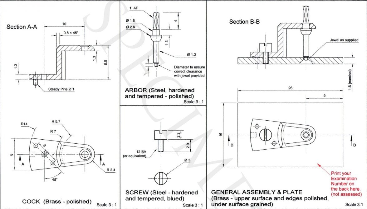
    So, I've touched on some of the others and time to bring D5 to the fore. Here’s an example of the sort of exam pieces you need to make in your workshop.
    0.jpg

    So, clearly, for this you need to have a lathe… Now, I’ve dithered a lot about which one to buy as I was not absolutely sure what attachments I would need. Having looked at new lathes and the cost involved, I thought it best to pick one up second hand with as many attachments as I thought necessary. Then I could upgrade later if I find I need to use this a lot.

    So, I bought from eBay a used Boley 8 mm lathe and it arrived last week. In the middle of this week, a motor arrived and I have now mounted all on a board. That delay was useful as it gave me time to strip it, clean, oil and check most of the attachments without the distraction of wanting to get cutting. You have no idea when you buy these if they are completely shot so, after cleaning and inspecting bearings, I checked run-out of the head/collets and set up the end float as well as checking that the tailstock runs true to the head. With some adjustment, all is well and I’m happy with it but, it could just as easily have been no use at all.

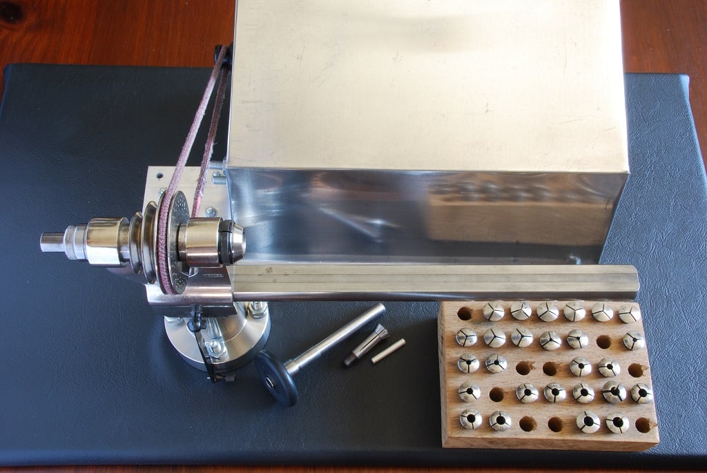
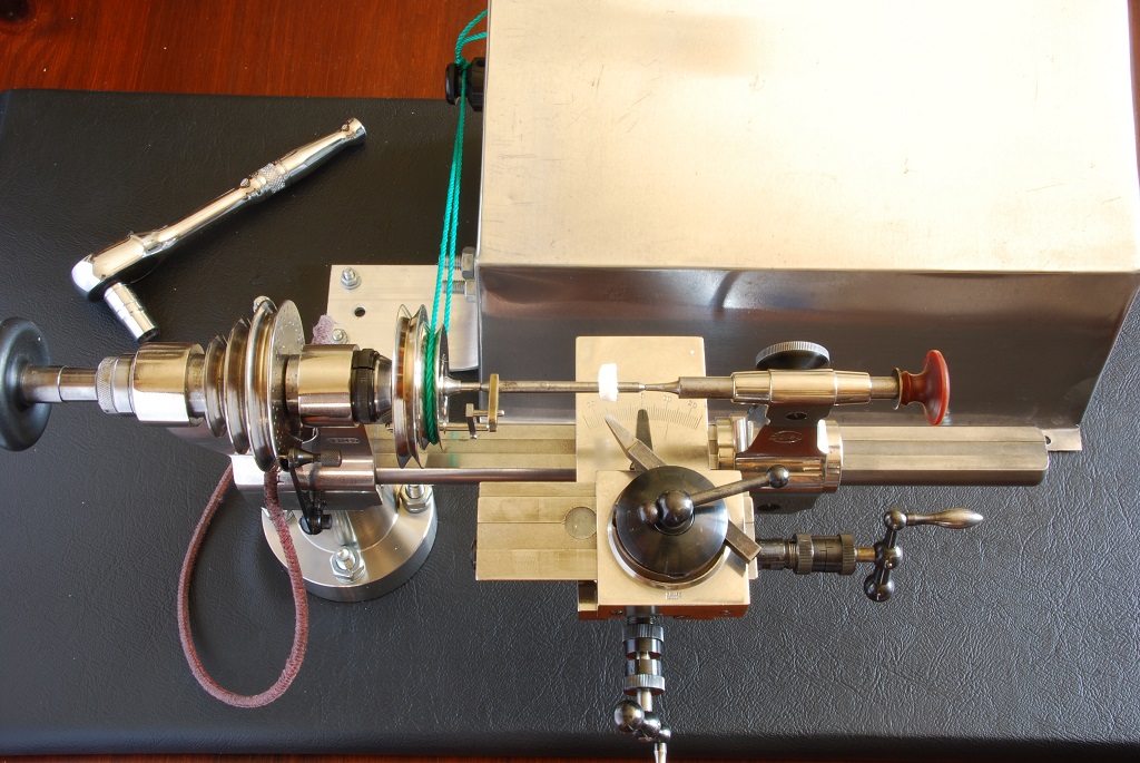
    Here, mounted on a board which I can clamp down to a workbench when in use. The rest of the time it can stay out as an ornament as I like to have it around.:) Need a clear plastic cover to keep the dust off though. Behind the lathe is the motor guard I knocked up yesterday in an hour from a piece of sheet aluminium in the garage. Looks not too bad and I will add a belt guard later - we should be careful around any machinery as they don't stop even when they've grabbed your hand/hair/clothes or spat a piece into your eye. Bear in mind that I haven't used a lathe since 1977 and that was a big proper engine lathe (bigger than a motorcycle, even a Harley:rolleyes:) which will quite happily kill you.

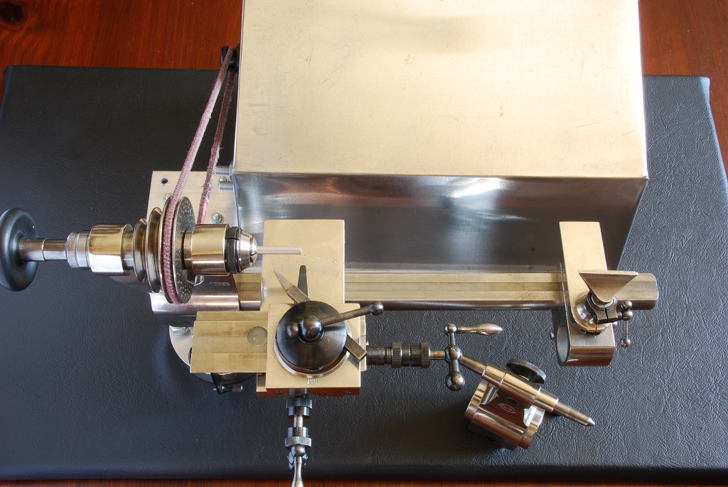
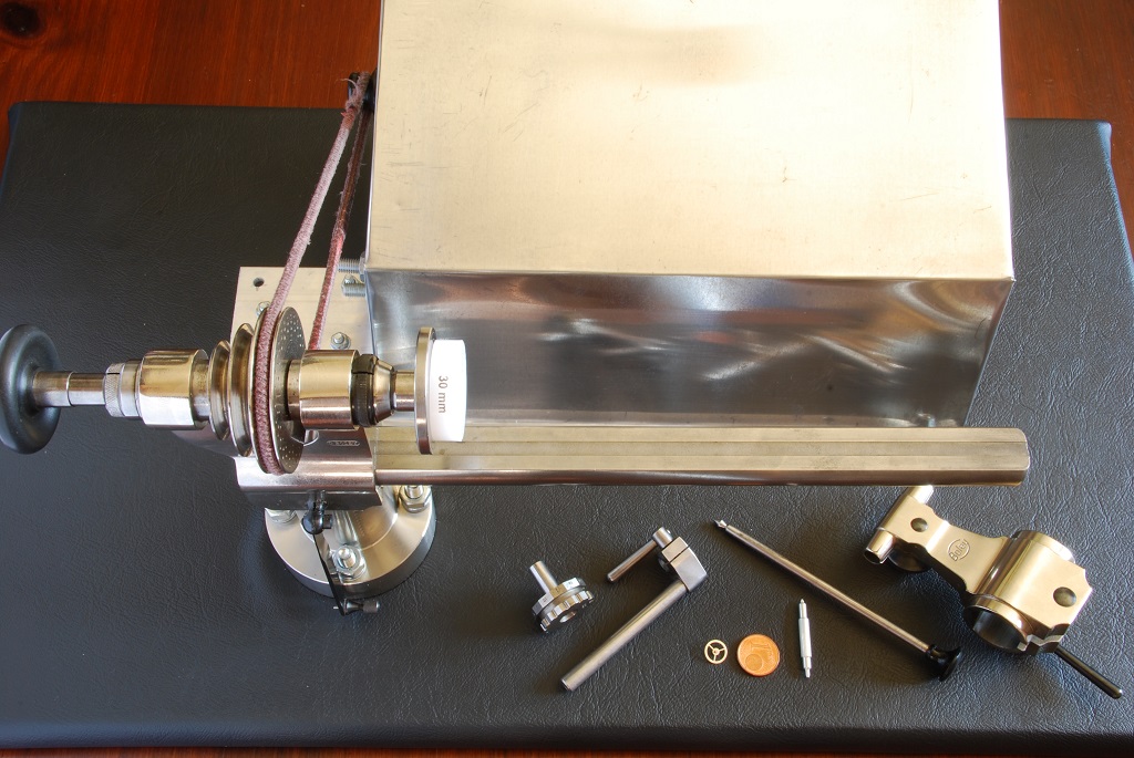
    This is the headstock, chuck and the bed. The maximum diameter of part that can be fitted is 90 mm as the offset of the head centerline is 45 mm from the bed and the bed is 260 mm long so this is small but, this is a standard size for Watchmakers. There are some smaller and larger but, I believe this is a good compromise – I’m feeling my way here. The drive is supplied by a variable speed motor through the belt and that turns the lathe – up to about 3000 rpm.

    The big thing to get going is having a selection of collets, which are typically available in 0.2 mm increments, that hold the job . So, the one out is a 3.8 mm collet and I’ll put a piece of 3.8 mm aluminium bar in it. The draw bar with the black handle goes in the left hand end and tightens the collet to grip the work. So, the collet and work turn as the lathe turns. Good selection of collets in the wooden box up to 6 mm diameter. I am repairing the big wooden box that holds everything as it's a bit fragile.
    1.jpg

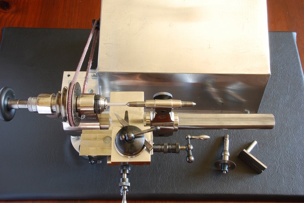
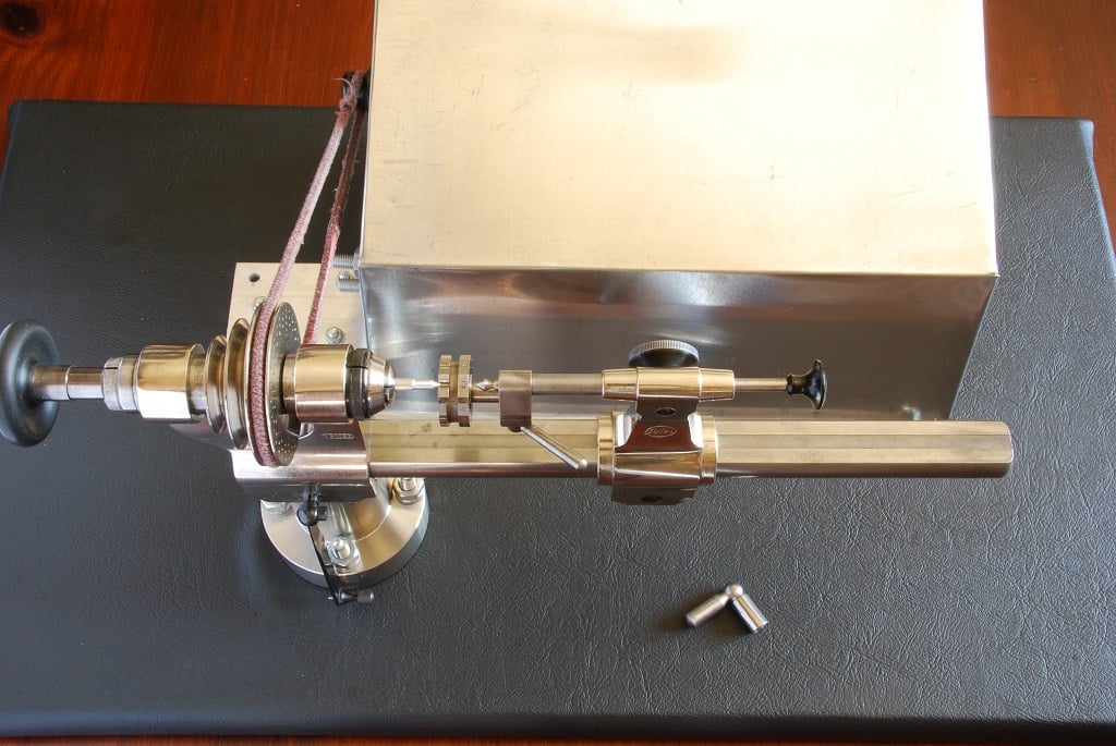
    Here with the work mounted and the cross slide fitted to the bed. You don’t need a cross slide and on the right hand end of the bed I’m showing a tool rest that you can use to work by holding the tool in your hand and bringing up to the work. On the top of the cross slide is the tool and you turn the two handles to move the slide/tool across the bed (closest handle) or along the bed (right hand handle). These little handles have a scale so, you can get some precision. The tail stock is shown on the board.
    2.jpg

    This is not the best set up for a lathe as the cutter forces the work sideways as it cuts which tends to distort the work and due to the offset from the front bearing, that bearing is reacting about twice that cutter force. This is what wears bearings, the side load. A better way to hold the work is to give it a centre support at its other end so that the cutter force is reacted there as well meaning the front bearing load is reduced by a factor of about 4. So, I cut a small recess in the end of the work, mount the tailstock with a pointed mandrel and bring it up to the end of the work so that it’s supported. This is not “turning between centres” as that’s for later but it does support the work better. On the board is the saw and table.
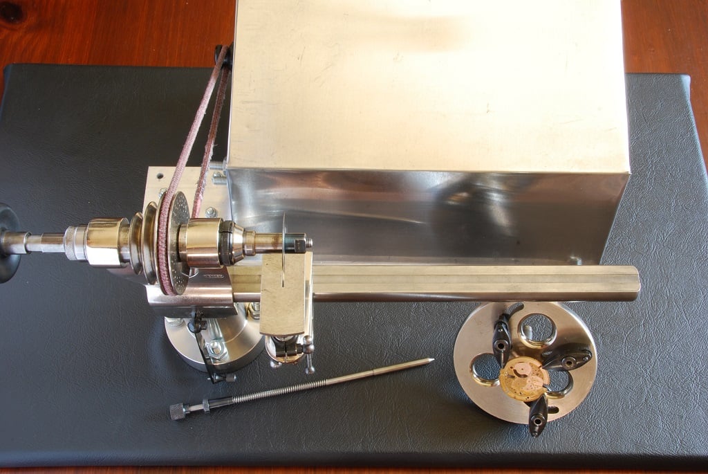
    3.jpg

    Here with the saw mounted in the chuck and the saw table fitted to the tool rest. This looks like a good way to remove parts of your fingers but it has it's uses for cutting parts, I suppose. On the board is the face plate and it's mandrel.
    4.jpg

    From here, I'm showing different ways of holding items ready for cutting with the tool, either manually with the tool rest or with the cross slide.

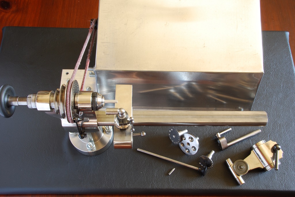
    The face plate looks very useful as it allows you to hold parts off centre by lining up a hole with the mandrel and then all your cutting is centred there. In this case, it's holding a 354 plate and it's centred on the barrel bearing. So now, the lathe centreline is on that barrel bearing. I do have a 352 where the barrel bridge is very worn at the hole for the barrel arbor (and they are not bushed) so, fitting as shown and then adding the barrel bridge means the lathe centreline has claimed the barrel axis ready to open out the bridge to take a bush. I'd aim to do this in two stages, one is drilling out the bridge and then reaming to the exact size for the bush. On the board is the tailstock and drilling attachment.
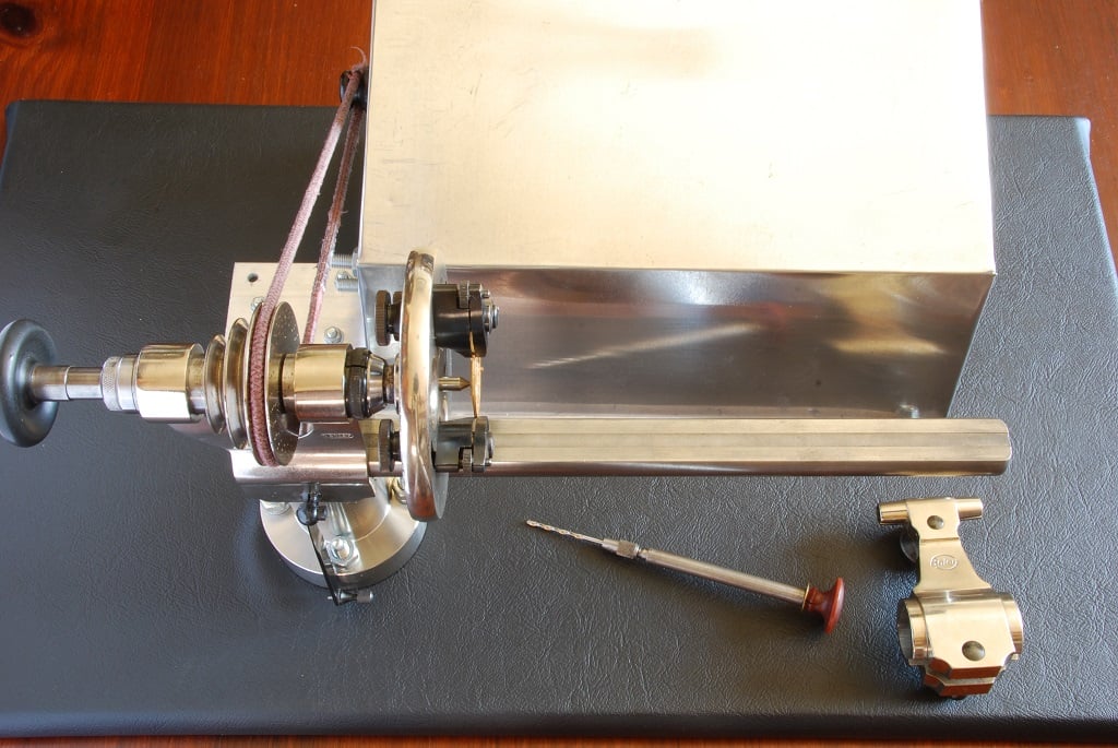
    5.jpg

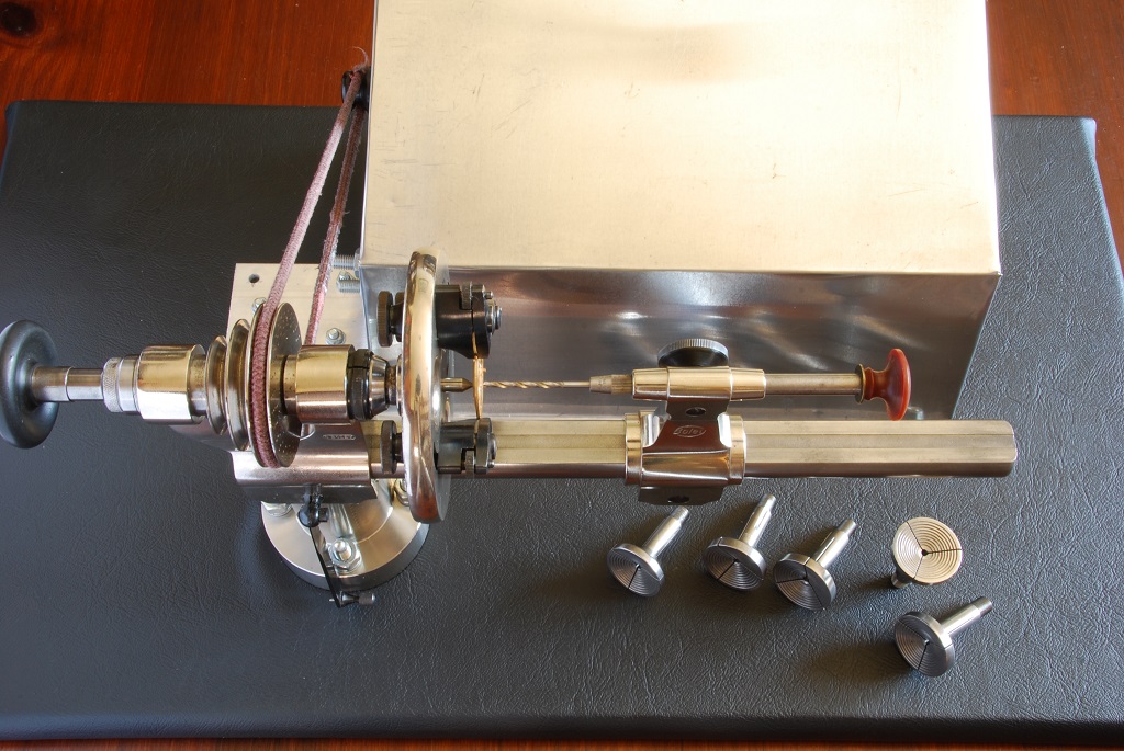
    Here with the tailstock mounted again and the drilling attachment lining up with the work. This is not the most accurate from of drilling but should be OK here. I'd like to be able to ream the hole here as well as it would be more precise for me than using the Seitz tool so, am working on a way to do that. On the board are the step chucks.
    6.jpg

    The five step chucks all look the same but are numbered 1 to 5 and are vary by 0.4 mm. Number 1 has 5.4 mm to 21.4 mm diameter steps in 2 mm steps but, number 2 is 0.4 mm bigger than number 1, number 3 a further 0.4 mm and so on. These can grip discs when tightened in the chuck and I've shown one gripping a crystal die - not that I'd cut something that heavy with this. On the board is the adjustable step chuck.
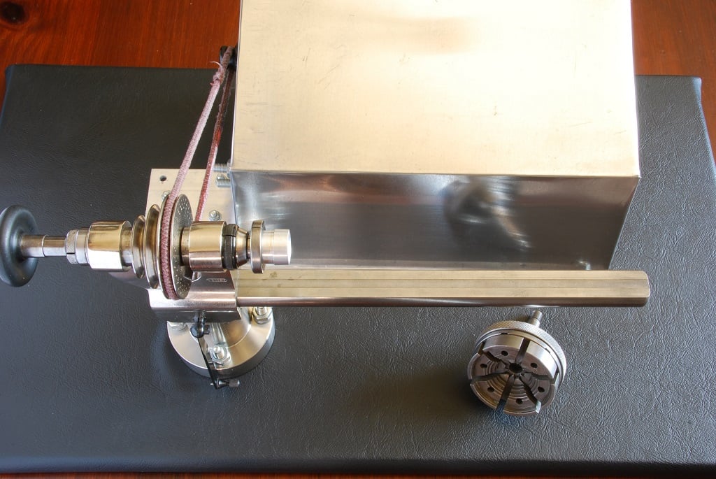
    7.jpg

    This adjustable chuck tightens by the knurled ring and goes up to 45 mm diameter. Shown here holding a much bigger crystal fitting die and on the board is the box chuck.
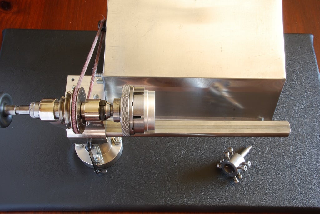
    8.jpg

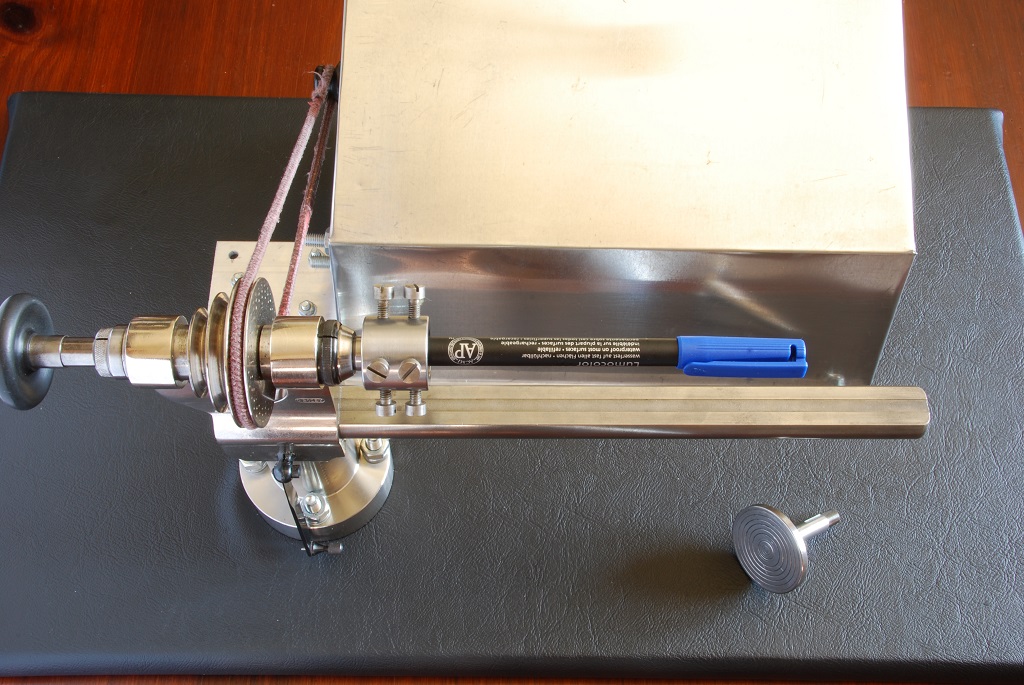
    Here the box chuck mounted and holding a pen as I have nothing of this diameter as an example:D. It goes up to 12 mm diameter so useful for items above 6 mm as that's the biggest for the collets but you have to centre the work by tightening the screws evenly so easy to get the work running off centre. On the board is a wax chuck.
    9.jpg

    The wax chuck is used to hold a flat disc using shellac or glue. The work is glued to the chuck, worked on and then unglued to separate it. I think most people use glue these days as shellac is a bit more difficult. Originally, I suppose it was wax based on it's name. On the board are a few things:
    Jacot drum and offset tailstock runner.
    A fairly small balance wheel and one cent coin.
    A little aluminium test piece I made yesterday - no particular size, just wanted to cut something. It's from 3.8 mm aluminium bar and I’m working with Aluminium at the moment as it’s easy to cut. You can see there is a big difference in scale for say a balance staff and my test piece is 2 to 4 times the size of the arbor in the exam piece above. You work down slowly in my opinion.
    The centering bar and the tailstock (again).
    10.jpg

    A few more pictures later explaining the Jacot drum and some other parts.

    Cheers, Chris
     
  20. ChrisN Aug 27, 2016

    Posts
    2,218
    Likes
    4,760
    So, continuing on.

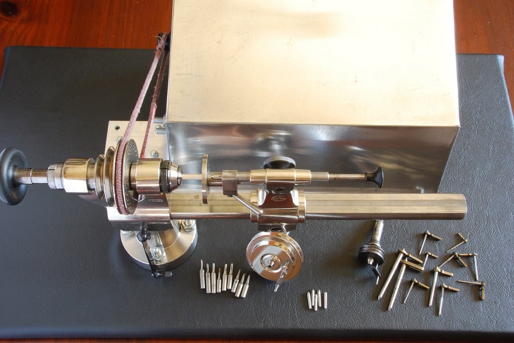
    The Jacot drum is used for burnishing pivots but is too large for watch pivots. In that case we use a specific piece of kit but, it is useful for clocks (wish I'd had this when I did my Smiths). It mounts on the tailstock via the offset runner which goes into the tailstock itself and allows you to line up any of the different sized grooves around the drum perimeter with the axis of the lathe chuck. This is done with the centering bar which goes down the centre of the the offset runner in the tailstock as shown below. Once the groove of choice is lined up with the lathe axis, the tailstock is locked off and the clock wheel fixed in the chuck with the appropriate collet. I don't have a good sized clock wheel to hand but I do have my little test piece so, it's shown in it's collet and, by definition, it sits in the groove on the Jacot drum. Fire up the lathe and use the burnishing tool (a bit like a very fine file) on the outside of the stationary drum to polish/burnish the pivot. Pretty neat as it's sitting exactly in the right place. On the board is the roller rest.
    11.jpg

    The roller rest is just used to be able to file shapes onto the work - for example a square on the end of a barrel arbor to accept the square hole in a ratchet wheel. It's mounted in the tool rest and the part showing to the left at 90 degrees is a roller so a file can be run across it without damaging it. In this case, the headstock chuck is locked off with the black bar on the left in the foreground which until now has been hanging down and it doesn't rotate. The index plate where it's locked has a series of holes around it so, an angle can be selected at each hole. File the flat with a standard file, rotate the chuck 90 degrees and lock again then file the next part of the square. I think a double roller rest might be more useful as it removes any possibility of error. These guys make them and I think I'll order one. On the board are the parts making up the "self aligning drill set".
    12.jpg

    The self aligning drill set has the three circular plates each with a chamfered set of holes. The drilling method in the previous post is not that accurate as the alignment of the work and drill are not well controlled. This solves that problem. Select a circular plate with a chamfer suitable for the work in question and the size of drill (in this case a pretty big chamfer with my 3.8 mm bar) and using the offset runner again, align it with the centering bar to the lathe axis and bring up to the work. Now that end of the work will run in the chamfer. Fit the drill in the small collet on the tailstock bar (shown above) and fire up the lathe to drill exactly down the centre of the work. Now, I don't have a drill to suit and I suspect you're meant to make your own flat drills but you can see where it should go, just to the right of the plate. On the board some parts for turning between centres.
    13.jpg

    There are two "turning between centres" carriers and I'm showing the bigger one here. In this usage, move the motor over 40 mm, lock the headstock chuck and fit the carrier to the headstock. The part that turns is now driven by the green cord (I need another belt as well as one to replace the main belt...). All those tapered pins have different size ends and one goes in the carrier chuck with an equivalent in the tailstock and neither turn. In this case, I'm showing the carrier chuck turning one of these tapered steel bars with the brass arms. That brass arm connects to a pin on the carrier chuck so that when it turns, the tapered shaft turns between the two centre ends. These are intended for turning bushes and the like which are fitted onto the tapered arms - now, again, I don't have a suitable size bush that is easily seen so, I've simulated it with a piece of pith::facepalm2::. Mounted like this, the outer diameter of the bush could be turned down but to reduce the thickness, I'd just mount it in a collet in the chuck.
    14.jpg

    So, the work could be mounted between those two centre ends and a driving dog clamped to the work so that it turns. This is the best way to use a lathe really, giving the most accurate results but, it turns out I don't have any driving dogs so will need to buy some. There are a few other useful items including one that is a carrier with safety line that is much smaller than the ones shown and intended for making balance staffs but the principle is the same as above.

    You can tell I'm quite pleased with my lathe:D

    Cheers, Chris