ChrisN
·Am not working today so am writing a little project. Some friends, knowing my interest in mechanical watches and that I spend a lot of my working day explaining how structures and mechanisms work, asked if I would show them the parts in a watch and what they do. I am putting the first sections here to see if it is of interest. It is likely to take me some time to complete and is a far more difficult to explain than even the mechanism of an aircraft pressure door....
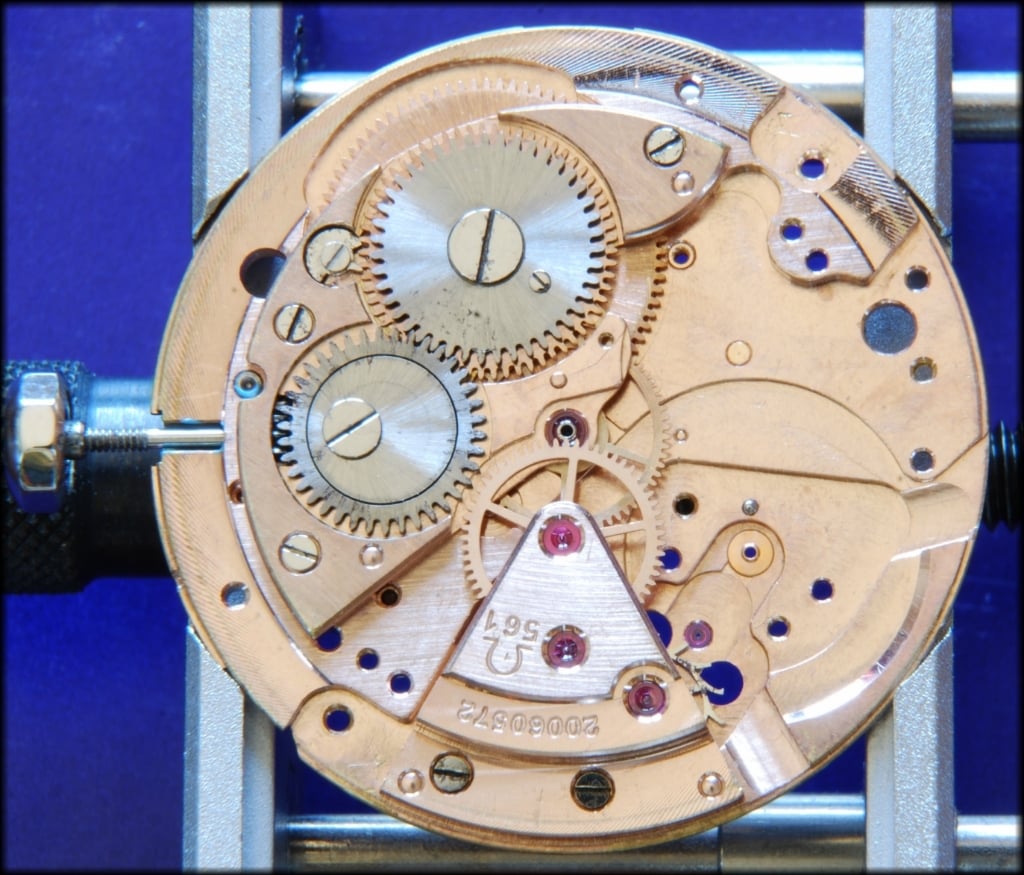
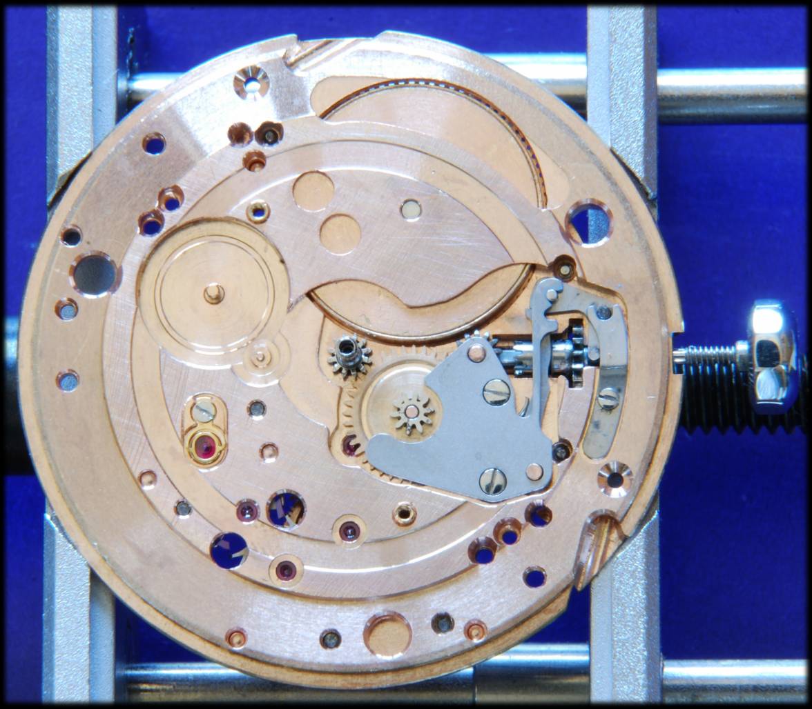
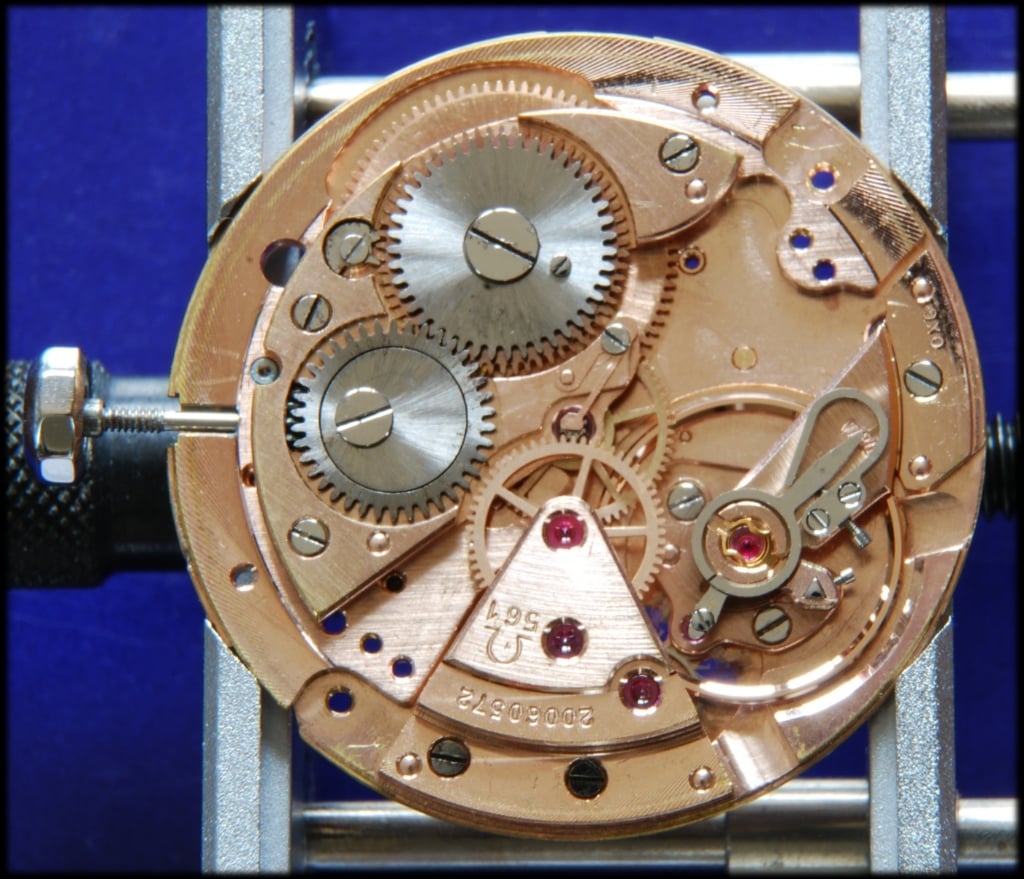
This is for a cal 561 (very similar to all cal 56x movements), which I took photos of during the rebuild and am trying to explain in a way that is not too technical. We leave the real watchmaking and technical questions for Al. This is not watchmaking anyway, just what the parts are there to do. There's no discussion of endshake, depthing or even wibble-wobble. Oil choices and wars thereof are also not included. It is simpler than that. Even some of the names have been simplified to, hopefully, make it clearer. This is also not exactly the order that I usually work but seemed best for the explanation and did involve some assembly/disassembly because of that. All corrections and clarifications are willingly received.
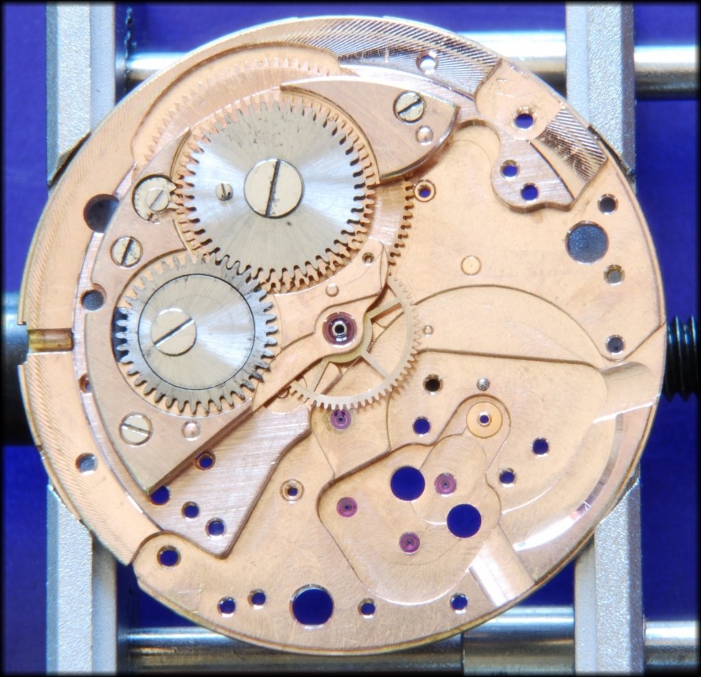
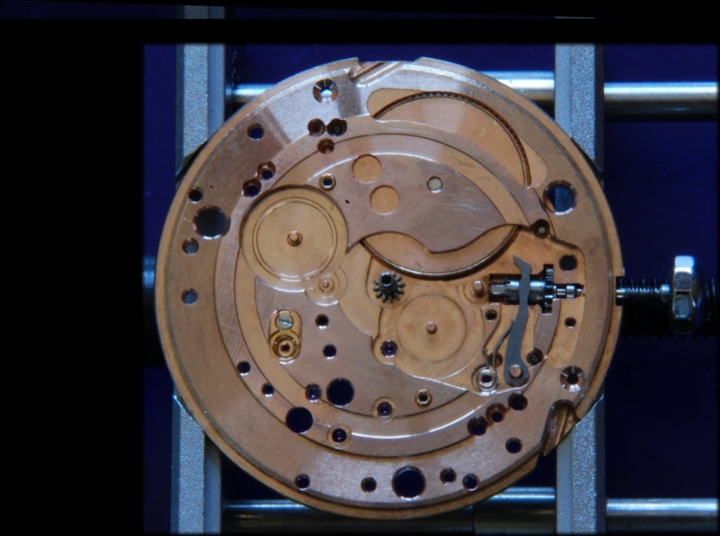
All photos are with 12 O'clock at the top so, when viewing the dial side, 3 O'clock is at the right and when viewing the back, 3 O'clock is on the left.
Firstly, the order of my explanation leaves the explanation of how the balance governs the release of energy until somewhat later so, clearly not the way a watch course would do it.
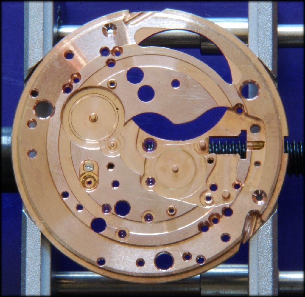
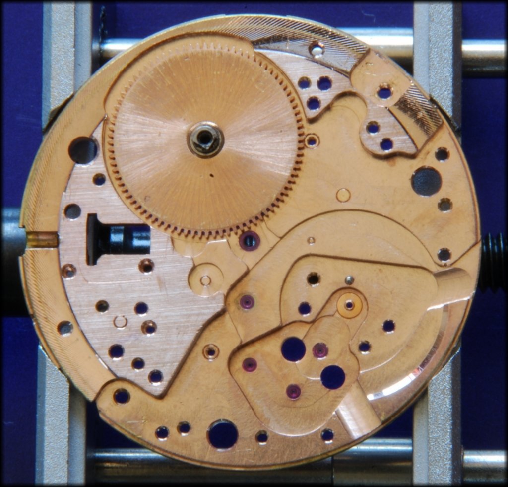
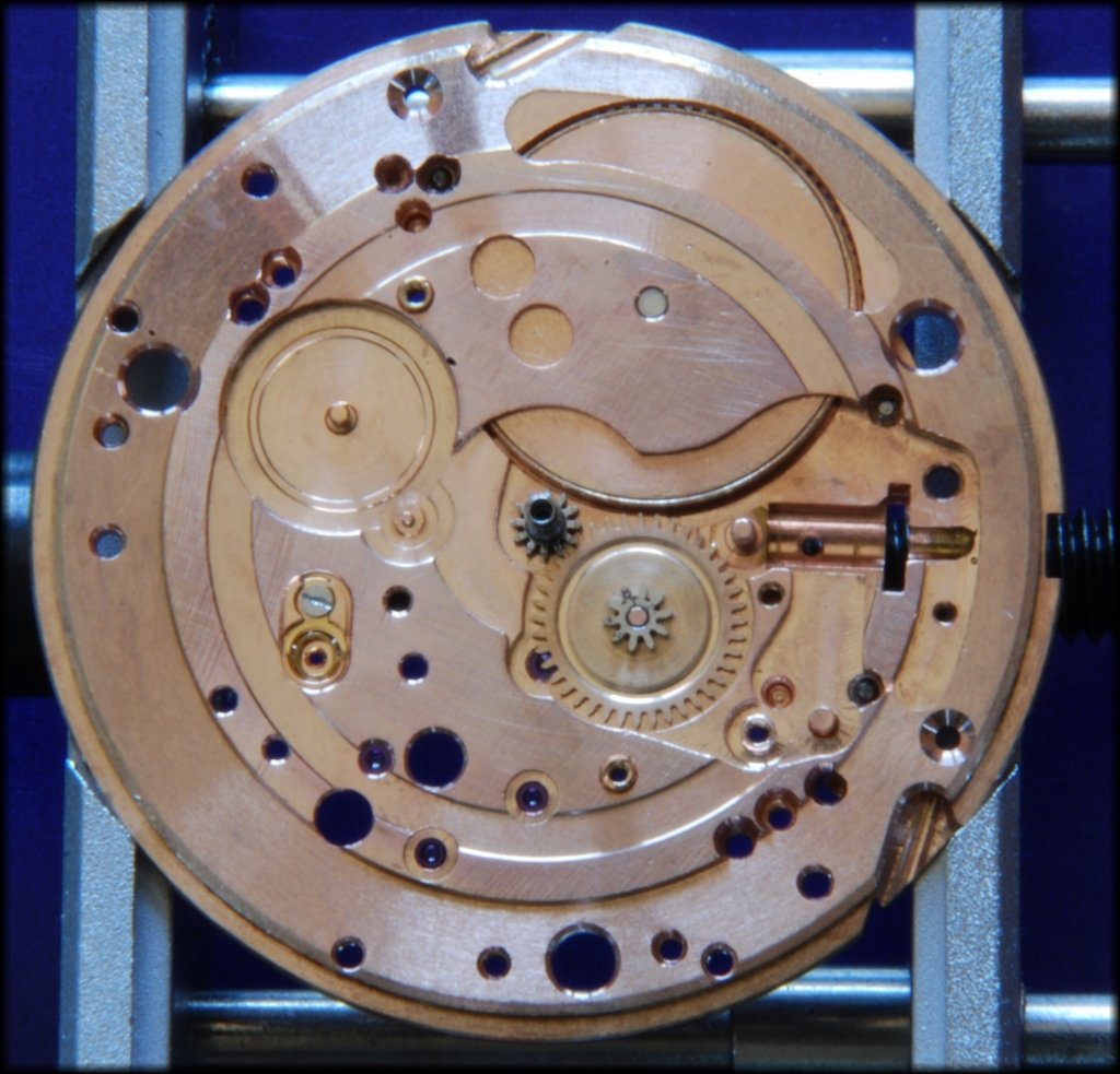
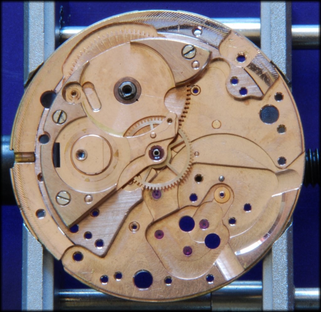
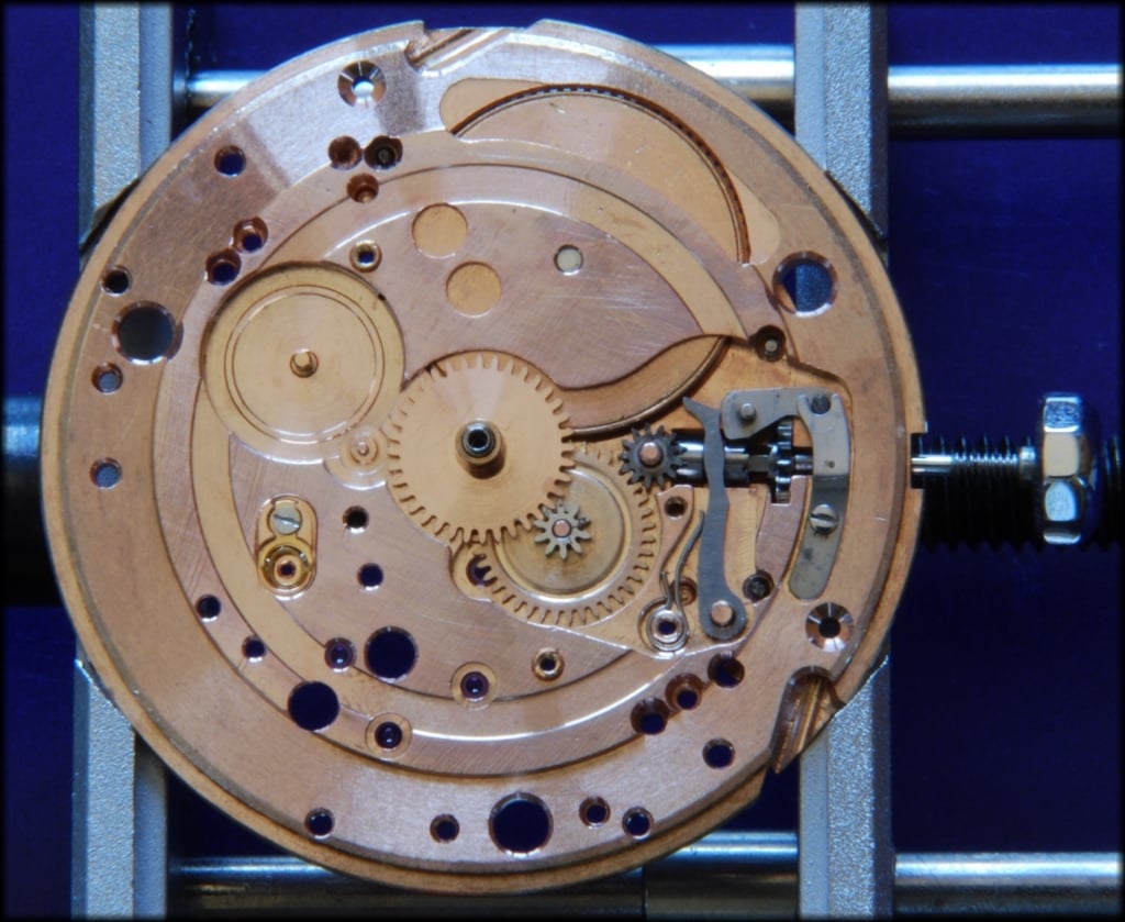
Fig. 1: This is a bare mainplate from the dial side. This is not a bad example although it is a bit marked in places. I seem to have a black mark on my camera as it is on every photo at about 11 O'clock and about a third out from the movement centre.
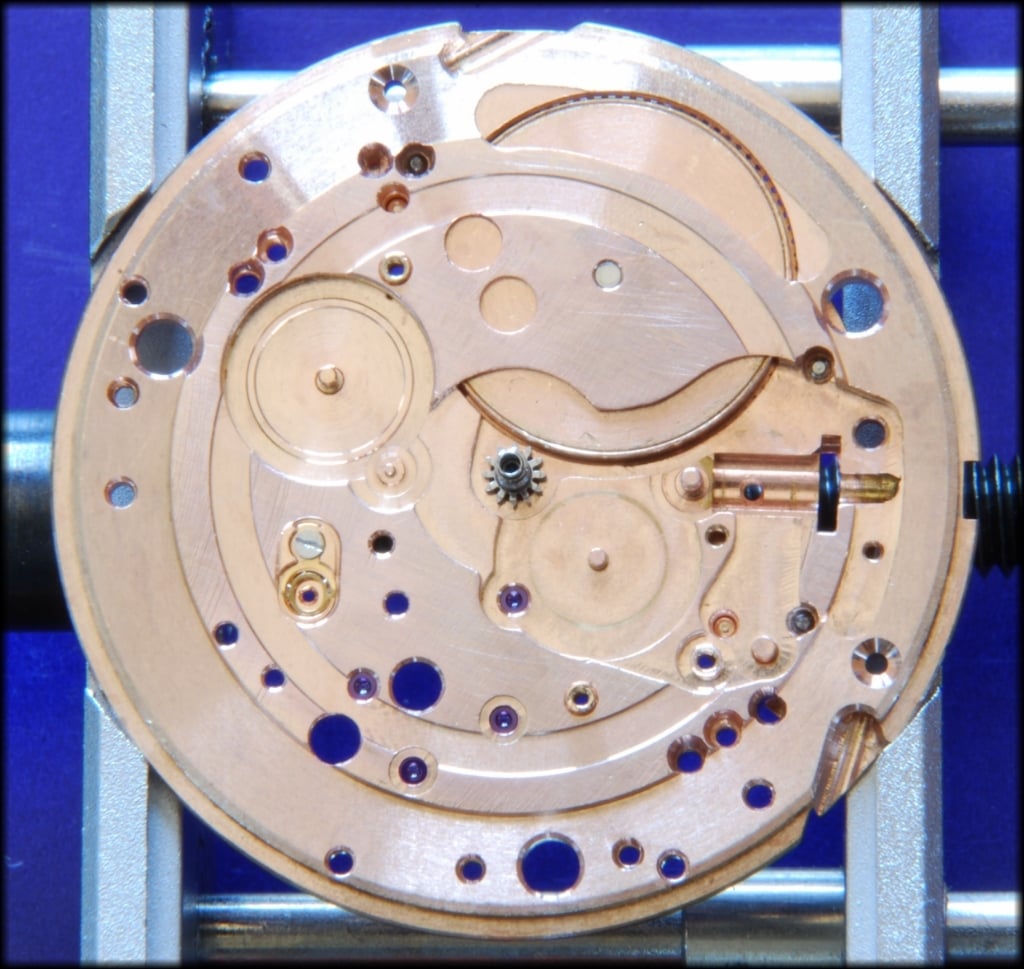
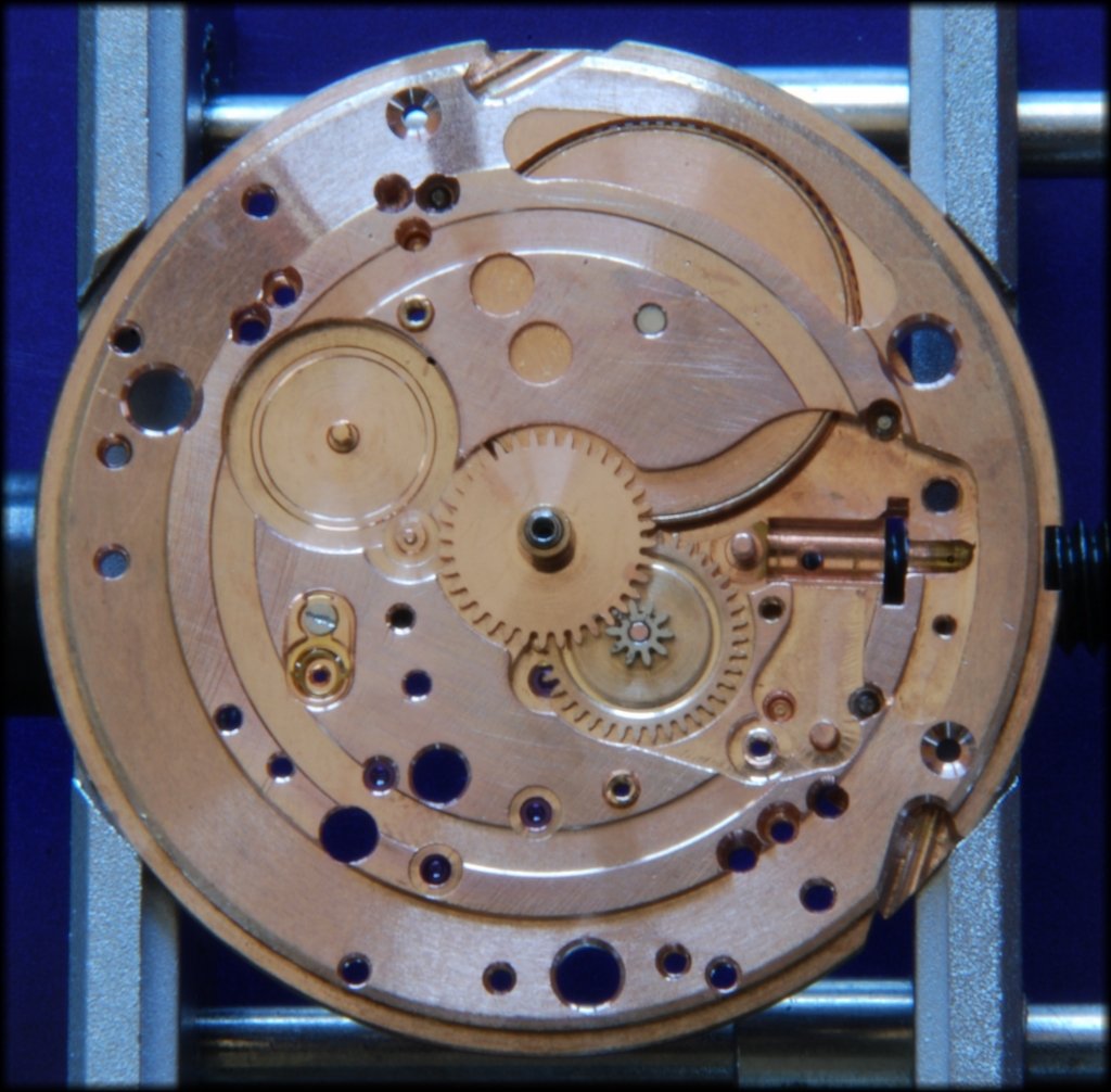
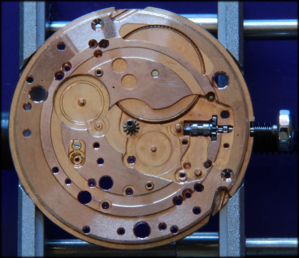
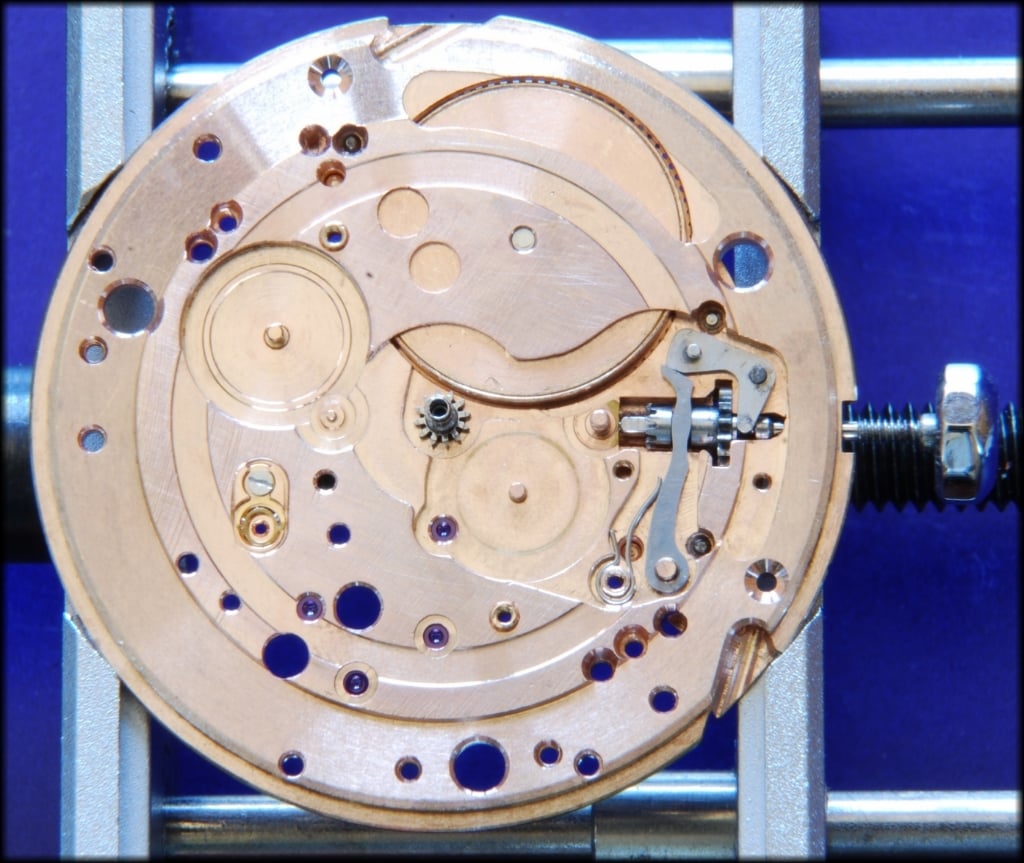
Fig 2: This is a bare mainplate from the rear side. You can see five purple coloured jewels here from the centre of the movement going down towards six O'clock and across to the right. These have a hole through the centre and are the bearings for the various wheels so that the shafts are not rotating directly in the mainplate.
I just know that if he sees this, Al will pick up on the staining at the third wheel jewel - I promise you, it has been cleaned three times (hand and ultrasonic) and that marking is part of the plate now!
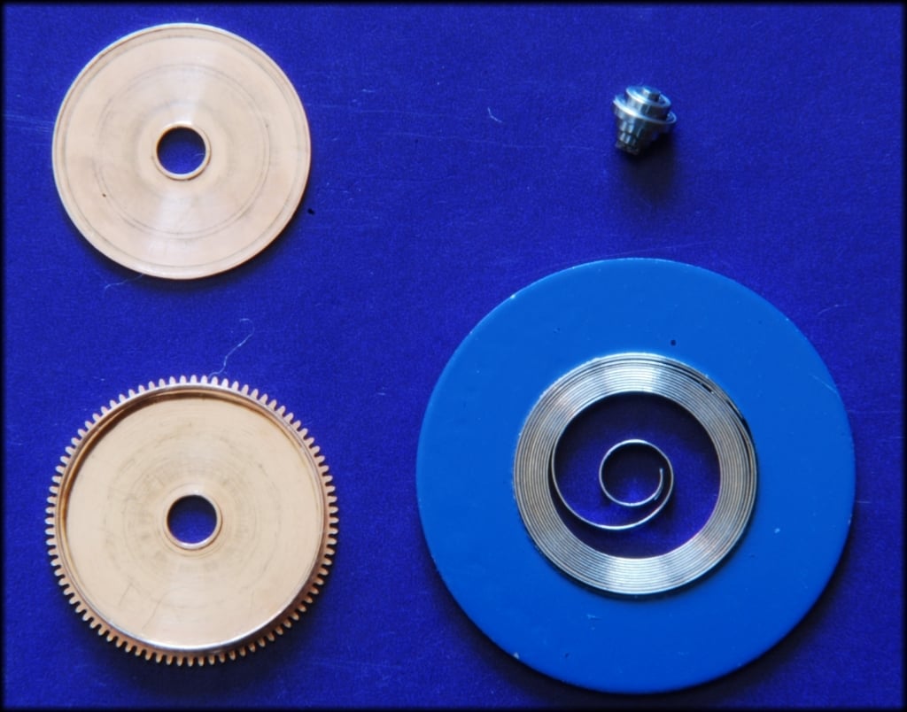
Fig 3: The barrel parts: the barrel lower left; the barrel closing plate above: the arbor to right and below that in the light blue ring is the mainspring. The lower end of the arbor is a square section, required later:
Fig 3a: The spring goes in the barrel and grips against the outer wall. I know, this is very basic! It is not aimed at Stewart for example... There is a little more to the way a spring grips the wall in an automatic but this is too complicated for the moment..
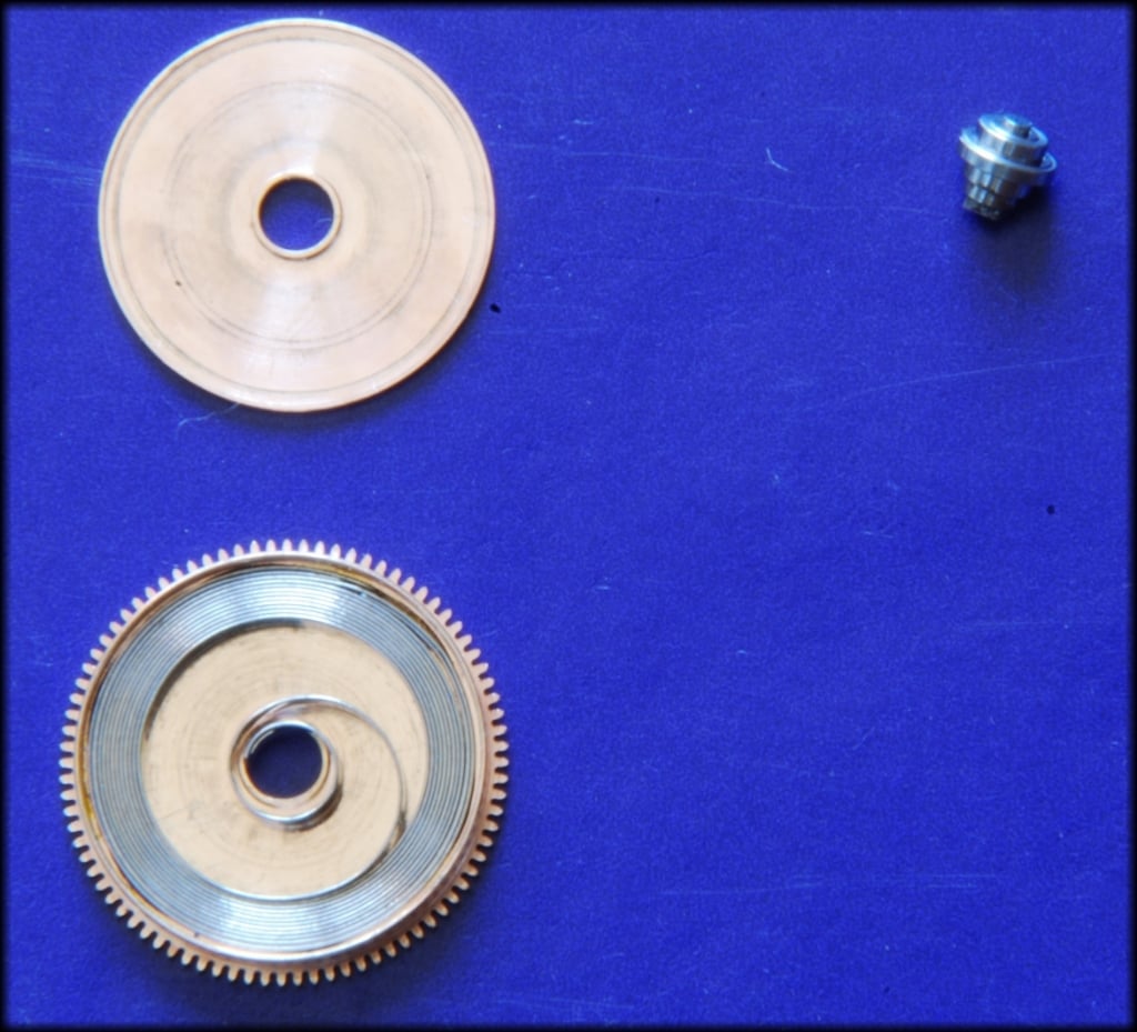
Fig 3b: The arbor (square section away from us) goes into the spring. The arbor grips the centre area of the spring so it's now connected to the barrel wall via the spring. If we hold the barrel wall and turn the arbor then we can tighten the spring so it stores energy. Then we can hold the arbor and release the barrel wall and the barrel will turn as the spring unwinds. This is what we use to power the watch.
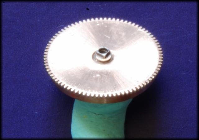
Fig 3c: Barrel closing plate added and turned over to show the square arbor section and the teeth on the barrel along the upper circumference.
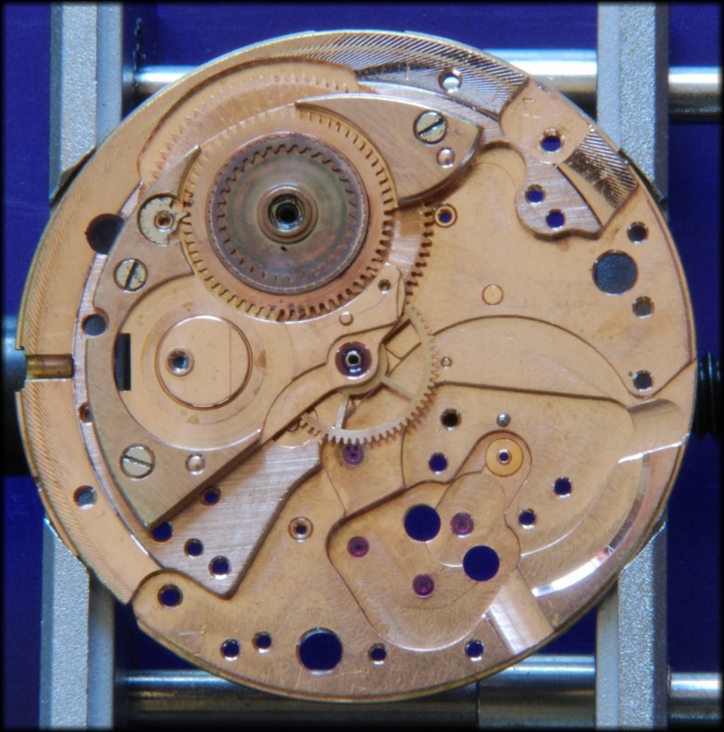
Fig 4: The barrel mounted in the mainplate. It will turn when the watch runs and the teeth on it are very close to the centre jewel to mesh with the 2nd wheel (or centre wheel here as it is at the centre of the movement):
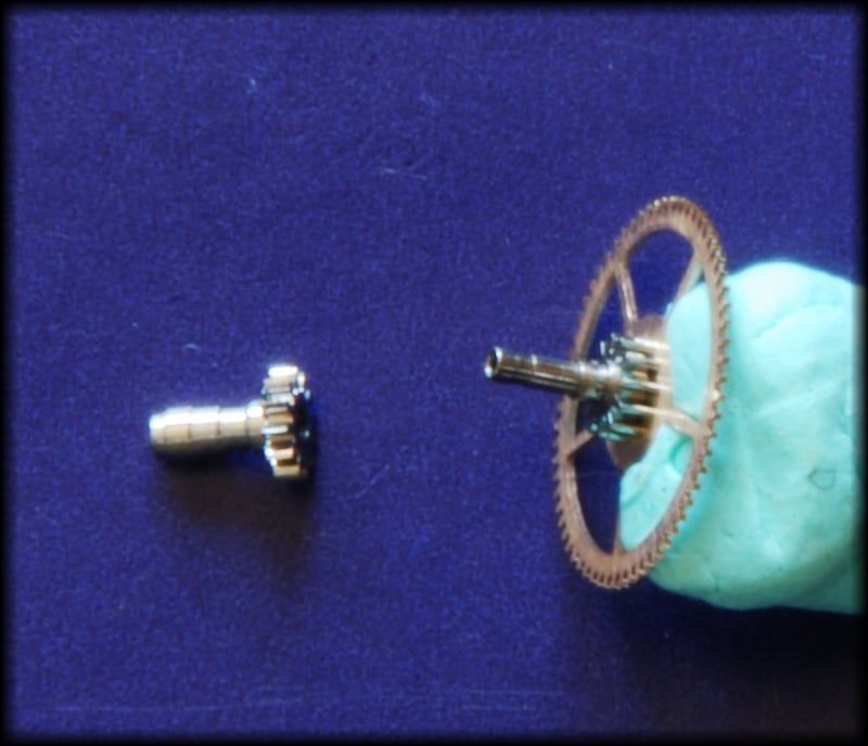
Fig 5: The centre wheel on the right and the cannon pinion on the left. The mainplate goes between these as the centre wheel shaft extends through the mainplate from the rear side. Note the centre wheel has a small steel gear underneath the large gear. The large gear controls the release of the spring energy but that is much later so, for the moment just assume that the balance will tell that gear when to move. The rest of the time it is locked and cannot rotate
The small gear will mesh with the barrel teeth as it is on the rear of the mainplate and the long hollow shaft goes through the plate to take the cannon pinion on the dial side of the plate. They are pressed together so, as the barrel rotates, the centre wheel and the cannon pinion rotate as well. This wheel turns once per hour.
Fig 6: The second wheel mounted on the rear of the plate (with cannon pinion pressed on the other side). The small steel gear has meshed with the barrel teeth.
Fig 7: The barrel plate attached by 3 screws is fitted which provides the support on this side for the barrel arbor (no jewel) and the jewelled support for the centre wheel.
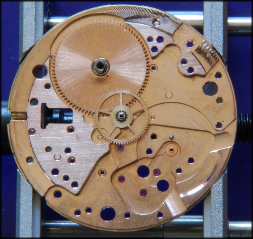
Fig 8: The dial side showing the cannon pinion. Note that it also has a gear. The minute hand will be pressed onto the outside of the cannon pinion later. You can also see that the barrel has filled in the big hole at the upper.
Fig 9: The cannon pinion gear meshes with a wheel on the mainplate shown in this picture. It is a pair of gears staked together - the large copper coloured one and the small steel one.
Fig 10: That steel gear meshes with this sleeve part that fits loosely over the cannon pinion and on here we will press the hour hand so, this one rotates once every twelve hours. I have to remove this and the previous wheel as turning the movement back over will cause them to fall off.
Continued in a minute as there are too many pictures...
