Omega Cal. 1320 vs 1325: Movement Differences & Repair

Posts
2,937
Likes
4,680
What is 134x?
134x is a way of writing 1340,1342,1343,1345 and 1346. These calibers all use the same motor.

You already have what you need for scanning to make a PCB in the photograph you circled.

I get zero ohms resistance in the bad motors and about 1.5k in the good motors.

My guess is Omega probably used the same coil across a range of calibers. That way they only needed one coil winder (which is a lathe. and a rotation counter) Sewing machine bobbin reminders are also coil winders. This can all be controlled by stepping motors. I have a custom winder for pipe organ magnet coils. (some which can be rewound using a drill press and a paper straw for a core.)

Resistance is determined by wire diameter, length and ohms law. The math for fitting the coils in the can is the same for figuring out how a mainspring fits in a barrel.

The linear lavete motors also have 1.5 to 1.7k in the maintenance sheet. The control chip may also be similar across calibers since etching chips is an expensive process. So they want to keep inventory on the low side.

Most likely these solder connections were done by hand, by women on an assembly line.

The wire gauge is really small probably somewhere around 60 to 120. Most coils are wound with 30 or so gauge. (larger number smaller wire.)

 
Posts
881
Likes
1,688
I really wish the OP luck brocade I can see he is putting this all together with love for the watch itself. In today’s world of flippers and hype, it’s nice to see someone caring enough to get one of these back to working condition.

That said, this is why I don’t play with quartz and electric watches. You have to learn to be an electrician. It was enough effort learning mechanical watches lol. They throw me enough curveballs.

Good luck to OP on his endeavours, keep us all posted on the journey. It’s very interesting.
 
Posts
18
Likes
1
134x is a way of writing 1340,1342,1343,1345 and 1346. These calibers all use the same motor.

You already have what you need for scanning to make a PCB in the photograph you circled.

I get zero ohms resistance in the bad motors and about 1.5k in the good motors.

My guess is Omega probably used the same coil across a range of calibers. That way they only needed one coil winder (which is a lathe. and a rotation counter) Sewing machine bobbin reminders are also coil winders. This can all be controlled by stepping motors. I have a custom winder for pipe organ magnet coils. (some which can be rewound using a drill press and a paper straw for a core.)

Resistance is determined by wire diameter, length and ohms law. The math for fitting the coils in the can is the same for figuring out how a mainspring fits in a barrel.

The linear lavete motors also have 1.5 to 1.7k in the maintenance sheet. The control chip may also be similar across calibers since etching chips is an expensive process. So they want to keep inventory on the low side.

Most likely these solder connections were done by hand, by women on an assembly line.

The wire gauge is really small probably somewhere around 60 to 120. Most coils are wound with 30 or so gauge. (larger number smaller wire.)

I will scan mine and post it here. The only issue I see with mine and comparing to the technical manual pictures - the end of the PCB I have is square and not rounded - so I have a suspicion that it actually is snapped off and I just simply don’t know it yet. Also one question - you already do have working motors. Can you maybe make an illustration/explain exactly which part of the motor (physically) should the two copper dots on the PCB touch? Is the PCB soldered onto the motor or is it MEANT to be able to be detached? Thank you very very much for your information!
 
Posts
2,937
Likes
4,680
maybe make an illustration/explain exactly which part of the motor (physically) should the two copper dots on the PCB touch?
Not quite sure I follow? The windings of the coil attach to the two solder points on the PCB.

On the 134x calibers there are springs on the electronics module what connects the traces. My guess this PCB is the difference between the calibers. Possibly as the manufactures were looking for the best way to handle this weak point.

The motors I have are glued and spot welded together. There is no indication that any of this can be serviced or replaced.
 
Posts
18
Likes
1
Not quite sure I follow? The windings of the coil attach to the two solder points on the PCB.

On the 134x calibers there are springs on the electronics module what connects the traces. My guess this PCB is the difference between the calibers. Possibly as the manufactures were looking for the best way to handle this weak point.

The motors I have are glued and spot welded together. There is no indication that any of this can be serviced or replaced.
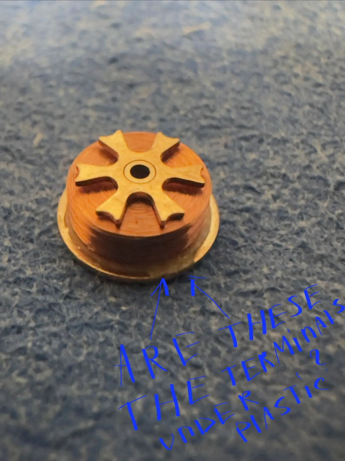
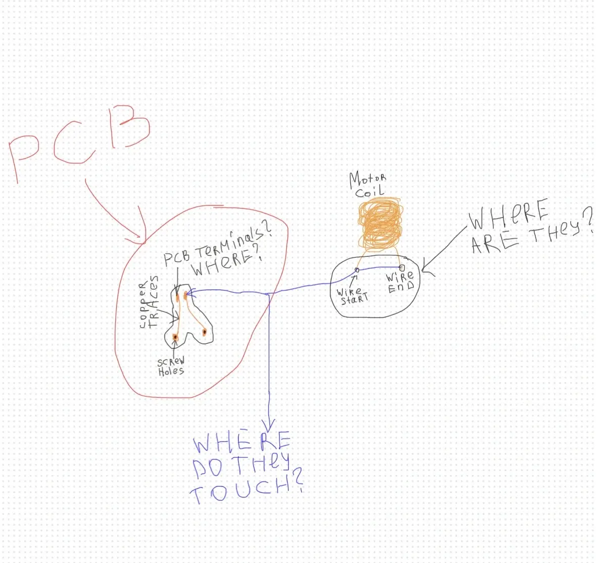
My question is actually precisely - WHERE do they touch?
I included my question in oonga-boonga picture style.

First question - I take off the lid of the motor - the lid and the coil are ONE module. Looking at the coil I don’t see its start and end. So how can I even measure the resistance? I really don’t understand.


Second question - looking at my previous post with the PCB both being in the motor and out of the motor - do I understand it correctly? One end of the coil goes into terminal A on the PCB. Another end of the coil goes into the terminal B on the PCB. The circuit is closed and has a coil now. Correct or not correct?

Third and the main question - where is the physical contact between the PCB and the coil wire even happening? I don’t get it.

Fourth question - when the watch was new - was the PCB attached to the coil directly forever? And now the fact that they are separate is an outcome of breakage and not design?

Pictures included:
 
Posts
2,937
Likes
4,680
Well that was a bust. I spent the morning letting google giggle tell about Time domain Reflectormitry. TDR. That only works on data cables with a return pair, like coax or Ethernet,

giggle suggested something called Inductive Signature Analysis or Ring Testing.

This told me how to test ignition coils.

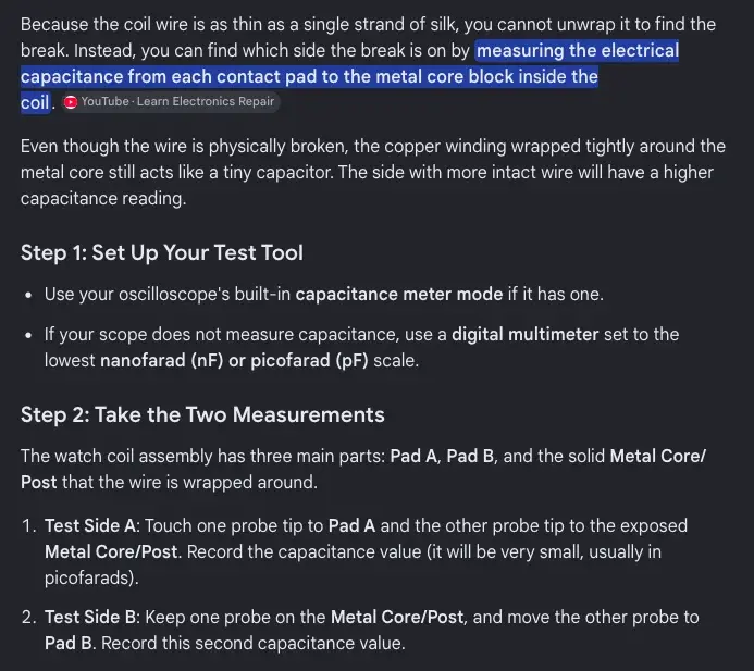
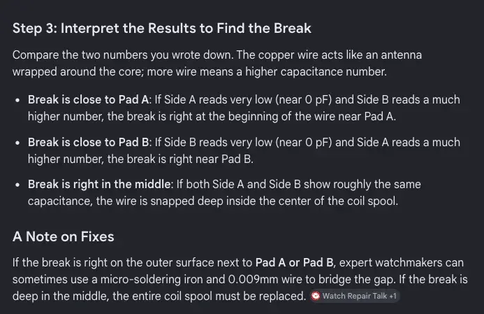
Eventually I got something about capacitive testing. This was the best it could do.

I think the wire is too thin to do anything with it to recover the broken ends. The wire is too far embedded into the resin block to find the ends.

The way my winder works is there is a wick which activates the insulation with alcohol. As the coil is wound a heat source melts the insulation together. This results in a solid block of wire and resin. There is no way to reverse this.

Most of giggle's reference sites to places like WRT. Say to toss the coil and replace it.

The only other option would be to make a new coil.

given that the caps on my coils are spot welded. There really is no practical way to fix a coil where the ends are broken at the place your drawing asks where are they? The wire is simply too thin to support rework. The pcb is glued to the coil preventing access. Removing it may have destroyed the cable I was trying to test.

I may dismember one of the other coils, but I doubt that there is much that can be done to repair it. Does seem frustrating that a tiny piece of wire renders the watch useless.

I started playing with the quartz as I was getting frustrated with kinked hairsprings. Guess that is the nature of watches. Dependent on the tiniest piece of coiled wire.
 
Posts
18
Likes
1
Well that was a bust. I spent the morning letting google giggle tell about Time domain Reflectormitry. TDR. That only works on data cables with a return pair, like coax or Ethernet,

giggle suggested something called Inductive Signature Analysis or Ring Testing.

This told me how to test ignition coils.

Eventually I got something about capacitive testing. This was the best it could do.

I think the wire is too thin to do anything with it to recover the broken ends. The wire is too far embedded into the resin block to find the ends.

The way my winder works is there is a wick which activates the insulation with alcohol. As the coil is wound a heat source melts the insulation together. This results in a solid block of wire and resin. There is no way to reverse this.

Most of giggle's reference sites to places like WRT. Say to toss the coil and replace it.

The only other option would be to make a new coil.

given that the caps on my coils are spot welded. There really is no practical way to fix a coil where the ends are broken at the place your drawing asks where are they? The wire is simply too thin to support rework. The pcb is glued to the coil preventing access. Removing it may have destroyed the cable I was trying to test.

I may dismember one of the other coils, but I doubt that there is much that can be done to repair it. Does seem frustrating that a tiny piece of wire renders the watch useless.

I started playing with the quartz as I was getting frustrated with kinked hairsprings. Guess that is the nature of watches. Dependent on the tiniest piece of coiled wire.
I am so sorry if it sounds a bit rude but could you please try to reply in a less vague way with less unrelated side info?
To just clarify - I am not sure my coil is broken and I never claimed it was. I just need to know how you measured the resistance in your coil? Where do I need to touch the probes IF the PCB is not attached? How did you manage? Because you did give me a resistance value - where do you have it from?

Other questions above are also a bit unrelated to that.
But the main question stays

-

Where do two terminals on the PCB and the coil itself touch physically? Where is that one precise point on the coil?
 
Posts
18
Likes
1
Well that was a bust. I spent the morning letting google giggle tell about Time domain Reflectormitry. TDR. That only works on data cables with a return pair, like coax or Ethernet,

giggle suggested something called Inductive Signature Analysis or Ring Testing.

This told me how to test ignition coils.

Eventually I got something about capacitive testing. This was the best it could do.

I think the wire is too thin to do anything with it to recover the broken ends. The wire is too far embedded into the resin block to find the ends.

The way my winder works is there is a wick which activates the insulation with alcohol. As the coil is wound a heat source melts the insulation together. This results in a solid block of wire and resin. There is no way to reverse this.

Most of giggle's reference sites to places like WRT. Say to toss the coil and replace it.

The only other option would be to make a new coil.

given that the caps on my coils are spot welded. There really is no practical way to fix a coil where the ends are broken at the place your drawing asks where are they? The wire is simply too thin to support rework. The pcb is glued to the coil preventing access. Removing it may have destroyed the cable I was trying to test.

I may dismember one of the other coils, but I doubt that there is much that can be done to repair it. Does seem frustrating that a tiny piece of wire renders the watch useless.

I started playing with the quartz as I was getting frustrated with kinked hairsprings. Guess that is the nature of watches. Dependent on the tiniest piece of coiled wire.
I am so sorry if it sounds a bit rude but could you please try to reply in a less vague way with less unrelated side info?
To just clarify - I am not sure my coil is broken and I never claimed it was. I just need to know how you measured the resistance in your coil? Where do I need to touch the probes IF the PCB is not attached? How did you manage? Because you did give me a resistance value - where do you have it from?

Other questions above are also a bit unrelated to that.
But the main question stays

-

Where do two terminals on the PCB and the coil itself touch physically? Where is that one precise point on the coil?


Dear sheepdoll,

Thank you again for your incredible patience with me - I know I've been asking a lot of questions and I really appreciate you taking the time to help someone with zero quartz movement experience. I'm genuinely grateful.

I'm sorry if I said your explanation was too vague earlier - that wasn't fair of me, I think the issue is more that I haven't asked my question precisely enough. Let me try to reformulate it properly this time, looking back at the photos I already posted above showing the PCB resting on top of the closed motor lid on confirmed-working eBay watches:

1. In those photos, is the PCB strip actually contacting the coil's wire ends through the closed lid somehow - or is it contacting the lid's metal surface itself?

2. If it's contacting the lid's metal surface - does the lid act as part of the electrical circuit (i.e., is the lid itself electrically connected to one end of the coil internally)?

3. If the lid is part of the circuit, why doesn't touching it with BOTH PCB contact points cause a short, given that it's one continuous solid piece of metal?

4. Is it possible that ONLY ONE of the two PCB contact points is electrically meaningful, and the other is just a mechanical spring/ground contact that doesn't matter where it lands?

5. Finally - in your own working motors, is the PCB strip permanently sealed inside before the lid closes, or is it removable/reseatable after the lid is already closed? I haven't been able to find out if mine is simply broken, or if this is by design.

Sorry again for so many questions in a row - I just really want to understand the actual physical path of electricity through this one specific component once and for all. Thank you so much, truly.
 
Posts
2,937
Likes
4,680
The two points are physically soldered to the PCB board.

The outside of the can and the frame of the watch is + common. The current (and voltage) through the coil alternates between + and minus. So there is a positive pulse, a rest period then a negative pulse followed by a second rest period.

I have not successfully been able to re connect broken wires from the coil to the PCB board. They are too fragile and break under the pressure of the tweezers.

When I did manage to pull two wire ends from the coil and tin them with solder I got zero resistance.

The coil resistance 1.5k comes from reading a number of data sheets. This is the same number the google AI regurgitates. It comes from Physics and the 'laws' what govern how elecromagnetisim work.

The PCB is probably glued on to the PCB before the wires are soldered to the contact points. That glue is probably an epoxy resin glue which is cured by a catalytic reaction. Removing this probably damaged the coil further.

My guess is the coil is wound first around a former. This assembly is probably then glued to the PCB and the wires soldered using a fixture. The armature is then added in a separate process. possibly after the coil is inserted in the can and the bottom cap spot welded on. The armature with the jewel settings can be pressed out even while still in the can. The stater and the top cap are separate pieces. Not all the motors I have seen have the top cap which helps to stabilize the steps.

I do realize this may come across as unrelated side info. It does however relate as I find it helps understand the underlying issue and why these motors fail.

I think we have the same problem, and a lot of the same frustration. Even though the calibers, 1342 and 1320 are different. That the PCB snapped off the base of the can.
 
Posts
18
Likes
1
The two points are physically soldered to the PCB board.

The outside of the can and the frame of the watch is + common. The current (and voltage) through the coil alternates between + and minus. So there is a positive pulse, a rest period then a negative pulse followed by a second rest period.

I have not successfully been able to re connect broken wires from the coil to the PCB board. They are too fragile and break under the pressure of the tweezers.

When I did manage to pull two wire ends from the coil and tin them with solder I got zero resistance.

The coil resistance 1.5k comes from reading a number of data sheets. This is the same number the google AI regurgitates. It comes from Physics and the 'laws' what govern how elecromagnetisim work.

The PCB is probably glued on to the PCB before the wires are soldered to the contact points. That glue is probably an epoxy resin glue which is cured by a catalytic reaction. Removing this probably damaged the coil further.

My guess is the coil is wound first around a former. This assembly is probably then glued to the PCB and the wires soldered using a fixture. The armature is then added in a separate process. possibly after the coil is inserted in the can and the bottom cap spot welded on. The armature with the jewel settings can be pressed out even while still in the can. The stater and the top cap are separate pieces. Not all the motors I have seen have the top cap which helps to stabilize the steps.

I do realize this may come across as unrelated side info. It does however relate as I find it helps understand the underlying issue and why these motors fail.

I think we have the same problem, and a lot of the same frustration. Even though the calibers, 1342 and 1320 are different. That the PCB snapped off the base of the can.
Thank you so much! 😊🙏
Now it is definitely super clear and I am very happy to read any side related/unrelated info! I was just struggling to understand if the PCB is a separate element or a part of the motor.
And for example the variation of the PCB being on top of the motor lid/inside - do you think it’s just a production variation where in one batch they kept the motor wires inside, and in another batch pulled them more towards the outside and put a PCB on top, but there are two wires underneath that we can’t see? Have you seen my previous pictures posted with both variations identifiable on the internet pictures of the same movement where in both cases the watch was marked as “working”? What’s your theory behind it? Thank you a thousand times, now I completely understand you.
 
Posts
18
Likes
1
The two points are physically soldered to the PCB board.

The outside of the can and the frame of the watch is + common. The current (and voltage) through the coil alternates between + and minus. So there is a positive pulse, a rest period then a negative pulse followed by a second rest period.

I have not successfully been able to re connect broken wires from the coil to the PCB board. They are too fragile and break under the pressure of the tweezers.

When I did manage to pull two wire ends from the coil and tin them with solder I got zero resistance.

The coil resistance 1.5k comes from reading a number of data sheets. This is the same number the google AI regurgitates. It comes from Physics and the 'laws' what govern how elecromagnetisim work.

The PCB is probably glued on to the PCB before the wires are soldered to the contact points. That glue is probably an epoxy resin glue which is cured by a catalytic reaction. Removing this probably damaged the coil further.

My guess is the coil is wound first around a former. This assembly is probably then glued to the PCB and the wires soldered using a fixture. The armature is then added in a separate process. possibly after the coil is inserted in the can and the bottom cap spot welded on. The armature with the jewel settings can be pressed out even while still in the can. The stater and the top cap are separate pieces. Not all the motors I have seen have the top cap which helps to stabilize the steps.

I do realize this may come across as unrelated side info. It does however relate as I find it helps understand the underlying issue and why these motors fail.

I think we have the same problem, and a lot of the same frustration. Even though the calibers, 1342 and 1320 are different. That the PCB snapped off the base of the can.

Dear sheepdoll,
What do you think about this?

My plan:

  1. Remove the motor lid completely
  2. Position the rotor/can upside down on a flat, stable surface
  3. Position the broken PCB piece on the same surface, aligning the original breakage point as precisely as possible under magnification
  4. Cut a thin piece of clear PVC (from something like a credit card or similar plastic) into roughly the shape of the PCB, to use as a temporary alignment splint over the repair area
  5. Carefully scrape away the thin insulating film/lacquer on the coil wire ends to expose bare copper, very gently, without applying tension to the wire
  6. Apply a minimal amount of BGA/chip reballing solder paste at the contact point
  7. Use a heat gun (not a soldering iron) at a controlled distance to reflow the paste - the idea being that the heat will also soften the PVC splint slightly, allowing it to passively conform around the wire and hold everything in alignment without any direct mechanical pressure from tools
  8. Once cooled, clean with IPA
  9. Apply a thin protective coat (nail polish or similar insulating varnish) over the repaired joint
  10. Remove the PVC splint if possible, or leave it in place as additional insulation
  11. Apply a final protective coat to the underside as well

The theory is that passive heat-conforming pressure from the softening plastic might succeed where direct tweezer pressure has failed for others, since it avoids ever mechanically gripping or pulling on the wire directly.